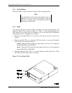
StorageWorks 8505 8mm Cartridge Tape Drive
2–2 Order Number: EK–STWCT–UG. E01
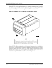
• SWXTE-AB: This option number identifies a configuration in which a second
cartridge tape drive is installed in a device carrier. For installation instructions, refer
to the same documents listed in the preceding bullet. In addition, this option is
always shipped with the document StorageWorks Family 5.25-inch SBB
Half-Height Device Installation Guide, which provides instructions on installing the
second cartridge tape drive in a device carrier.
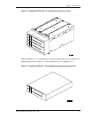
• SWXTE-AC: This option number identifies a configuration in which a cartridge
tape drive is installed in a desktop expansion unit. For installation instructions, refer
to the document titled StorageWorks Desktop Expansion Unit User's Guide.
2.3 Performing the Initial Power On
After you have installed the cartridge tape drive, you can perform the initial power on
procedure. Power on is accomplished by installing the tape drive into its desktop
expansion unit or expansion storage pedestal cabinet, and then applying power to the
cabinet.
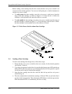
When you apply power, the drive performs its power-on initialization and self-test
(POST). Assuming that no data cartridge is loaded and that the tape drive is connected
correctly, POST takes about 30 seconds as follows:
• During the first part of POST, all three LEDs will be lit.
• During the second part of POST, the top amber LED will be lit and the middle and
bottom LEDs may flash depending on whether the tape drive is connected to the
SCSI bus and a data cartridge is loaded.
NOTES
Do not insert a data cartridge into the tape drive while POST
is in progress because the drive will automatically eject it.
If the top amber LED does not go out after POST, an error
has occurred. Contact your vendor.
When POST completes (top amber LED off), the tape drive is ready for normal
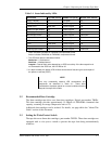
operation. After POST completes, you should refer to Table 3–1 in Chapter 3 if the state
of the LEDs differs from the state described in this procedure. The table shows how to
determine the drive’s operating state by the behavior of the LEDs.


