


16
HP 8753ET/ES supplemental
characteristics
Measurement
Number of display channels
Four display channels available.
Number of measurement channels
Two primary and two auxiliary measurement channels
available.
Measurement parameters
HP 8753ET: Reflection, transmission, A, B, R, A/R, B/R,
A/B. Conversion to impedance or admittance.
HP 8753ES: S11, S21, S12, S22, A, B, R, A/R, B/R, A/B.
Conversion to impedance or admittance.
Formats
Cartesian:
log/linear magnitude, phase, group delay,
SWR, real and imaginary.
Smith chart: with log/linear amplitude and phase,
R + jX, G + jB, or real/imaginary markers.
Polar: with linear/log amplitude, phase, or real and
imaginary markers.
Data markers
Each display channel has five independent markers
that can be displayed simultaneously. Twenty indepen-
dent markers can be displayed in 4-channel display
mode when markers are uncoupled.
Marker functions
Markers can be used in various functions: Marker
search (Mkr to max, Mkr to min, Mkr to target), Mkr
bandwidth with user-defined target values, Mkr to
start, Mkr to stop, Mkr to center, Mkr to span, Mkr to
reference, Mkr to delay, and trace statistics (average
value, standard deviation, and peak-to-peak deviation
of the data trace between two markers). The tracking
function enables continuous update of marker search
values on each sweep.
Group delay characteristics
Aperture: selectable
Maximum aperture: 20% of frequency span
Minimum aperture: (freq. span) / (number of points
+1)
Range
The maximum delay is limited to measuring no more
than 180˚ of phase change within the minimum aper-
ture. Range = 1 / (2 x minimum aperture)
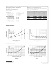
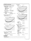
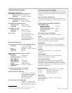
Accuracy
The following graph shows group-delay accuracy at
1.3 GHz with type-N full two-port calibration and
10-Hz IF bandwidth. Insertion loss is assumed to be
< 2 dB and electrical length to be ten meters.
Source control
Sweep limits
Set start/stop or center/span of the stimulus parameter
(frequency, power, time) directly through the source
control keys and the control knob, the step keys or the
data entry keyboard.
Sweep type
Set a linear or logarithmic sweep, an arbitrarily defined
frequency list, a power sweep or a CW (single frequen-
cy) type of sweep.
Measured number of points per sweep
Linear frequency: choose 3, 11, 26, 51, 101, 201, 401,
801, or 1601 points.
Fast swept list
Define up to 30 different sub-sweep frequency ranges
in any combination of CW, center/span, or start-stop
sweep modes. Set test-port power levels and IF band-
width independently for each segment.
Sweep modes
Set a coupled channel sweep (same stimulus condi-
tions on both channels) or an uncoupled channel
sweep.
Chop/alternate
Select whether to alternately or simultaneously (chop)
measure channels when in dual-channel mode. Chop
mode is faster, while alternate mode optimizes dynam-
ic range.
Sweep time
Set sweep time in seconds, minutes or hours.
Automatic sweep time
Select auto sweep time by entering zero seconds
sweep time. The analyzer will sweep at the minimum
sweep time for any subsequently selected stimulus
conditions. Auto sweep time is the default condition.