


22
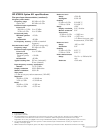
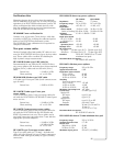
Test set specifications for Option 011
HP 85046A/B S-parameter test sets
The HP 85046A/B S-parameter test sets provide the
capability to measure reflection and transmission char-
acteristics (including S-parameters) of two-port
devices in either direction with a single connection.
The test sets are controlled from the HP 8753ES
Option 011 and include a programmable step attenua-
tor. The frequency range of the HP 85046A 50-ohm
test set is 300 kHz to 3 GHz. The HP 85046A has preci-
sion 7-mm connectors. The frequency range of the
HP 85046B 75-ohm test set is 300 kHz to 2 GHz. The
HP 85046B has 75-ohm type-N(f) connectors. Both
connectors can be adapted to other interfaces with
the appropriate precision adapters.
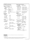
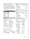
HP 85046A/B Specifications
Note: Specifications that apply only to the HP 85046
are indicated in parentheses.
Impedance
50 ohm (75 ohm)
Frequency range 300 kHz to 3 GHz
(300 kHz to 2 GHz)
Directivity 35 dB to 1.3 GHz
30 dB to F
max
1
Typical tracking
Transmission magnitude, phase
2
0.3 MHz to 2.0 MHz ±1.5 dB, ±20˚
2.0 MHz to F
max
±1.5 dB, ±10˚
Reflection magnitude, phase
2
0.3 MHz to 2.0 MHz ±1.5 dB, ±25˚
2.0 MHz to F
max
±1.5 dB, ±10˚
Effective source match
0.3 MHz to 2.0 MHz 14 dB
2.0 MHz to 1.3 GHz 20 dB (17 dB)
1.3 GHz to F
max
16 dB
Nominal insertion loss
Input to test port
14 dB + 0.5 dB/GHz
(19.5 dB + 1 dB/GHz)
Input to incident 18 dB + 1.5 dB/GHz
(18 dB + 1.5 dB/GHz)
Port 1, 2 to A, B 6.5 dB + 1.0 dB/GHz
(12 dB + 0.5 dB GHz)
Test set switch/repeatability
±0.03 dB; ±0.01 dB
3
Max. operating level +20 dBm
Damage level +30 dBm
RF attenuator range 70 dB, 10 dB steps
DC bias range ±30 VDC, 200 mA
4
500 mA max
DC bias connectors 50 ohm BNC (f)
Includes four 190 mm (7.5 in) type-N
cables and test set
interconnect cable.
Dimensions
90 mm H x 432 mm W x 553 mm D
Weight 9.1 kg (20 lb)
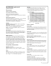
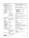
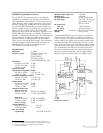
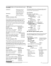
A standard HP 85046A/B test set contains a solid-state
transfer switch, which allows continuous switching of
power from port 1 to port 2 for full two-port error cor-
rection. Option 009 replaces the transfer switch with a
mechanical switch. This provides about 1.5 dB more
power at the test port, but does not allow continuous
switching, so the user must initiate updates of all four
S-parameters for full two-port error correction. Also,
the mechanical switch has relays that will wear out
faster than the solid-state switch. Approximate lifetime
of the mechanical switch is 1 million cycles.
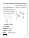
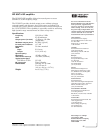
HP 85046A schematic
1. F
max
is the upper frequency limit of the associated test set.
2. Degrees, specified as deviation from linear phase.
3. Typical performance.
4. Some degradation of RF specifications may occur.