


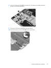
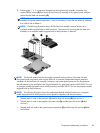
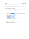

5.
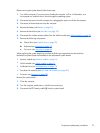
Following the 1, 2, 3, 4 sequence stamped into the fan/heat sink assembly, loosen the four
captive Philllips screws (2) that secure the fan/heat sink assembly to the system board, and then
remove the fan/heat sink assembly (3).
NOTE: Due to the adhesive quality of the thermal material located between the fan/heat sink
assembly and system board components, it may be necessary to move the fan/heat sink assembly
from side to side to detach it.
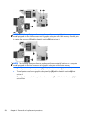
NOTE: The following illustration shows the fan/heat sink assembly removal process for a
computer model equipped with an AMD processor. The process for removing the fan/heat sink
assembly on a computer model equipped with an Intel processor is identical.
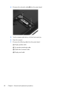
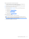
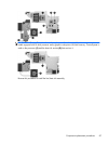
NOTE: The thermal material must be thoroughly cleaned from the surfaces of the heat sink and
the system board components each time the heat sink is removed. Replacement thermal material is
included with the fan/heat sink assembly, processor, and system board spare part kits. Replacement
thermal material is also available in the Thermal Material Kit, spare part numbers 685348-001 (for use
on computer models equipped with an AMD processor) and 682100-001 (for use on computer models
equipped with an Intel processor).
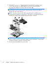
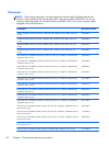
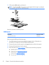
NOTE: The following illustration shows the replacement thermal material locations on a computer
model equipped with an AMD processor and a graphics subsystem with discrete memory.
●
Thermal paste is used on the processor (1) and the heat sink section (2) that services it
●
Thermal paste is used on the graphics subsystem chip (3) and the heat sink section (4) that
services it
●
Thermal pads are used on the system board components (5) and the heat sink sections (6) that
service them
Component replacement procedures
85