


Fan/heat sink assembly
NOTE: All fan/heat sink assembly kits include replacement thermal material.
Description Spare part number
Fan/heat sink assembly for use in UMA models in which the processor is not soldered to the
system board
636940-001
Fan/heat sink assembly for use in UMA models in which the processor is soldered to the system
board
642731-001
Fan/heat sink assembly for use in models with discrete graphics 636939-001
NOTE: To properly ventilate the computer, allow at least a 7.6 cm (3 inch) clearance on the right
side and rear panel of the computer. The computer uses an electric fan for ventilation. The fan is
controlled by a temperature sensor and is designed to turn on automatically when high temperature
conditions exist. These conditions are affected by high external temperatures, system power
consumption, power management/battery conservation configurations, battery fast charging, and
software requirements. Exhaust air is displaced through the ventilation grill located on the left side of
the computer.
Before removing the fan/heat sink assembly, follow these steps:
1. Shut down the computer. If you are unsure whether the computer is off or in Hibernation, turn
the computer on, and then shut it down through the operating system.
2. Disconnect all external devices connected to the computer.
3. Disconnect the power from the computer by first unplugging the power cord from the AC outlet
and then unplugging the AC adapter from the computer.
4. Remove the battery (see
Battery on page 36).
5. Remove the following components:
a. Hard drive (see
Hard drive on page 43)
b. WLAN module (see
WLAN module on page 40)
c. Optical drive (see
Optical drive on page 45)
d. Keyboard (see
Keyboard on page 47)
e. Top cover (see
Top cover on page 49)
f. Speaker assembly (see
Speaker assembly on page 68)
g. Power connector cable (see
Power connector cable on page 64)
h. USB board (see
USB board on page 63).
i. Display assembly (see
Display assembly on page 56)
j. Bluetooth module removal (see
Bluetooth module on page 66)
k. System board (see
System board on page 70)
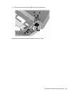
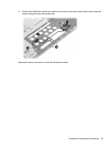
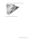
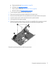
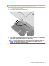
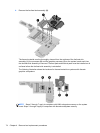
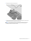
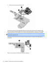
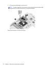
Remove the fan/heat assembly (fan/heat sink appearance may vary):
72 Chapter 4 Removal and replacement procedures