


5–38 Maintenance and Service Guide
Removal and Replacement Procedures
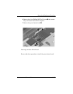
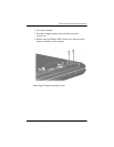
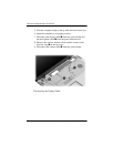
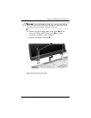
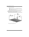
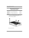
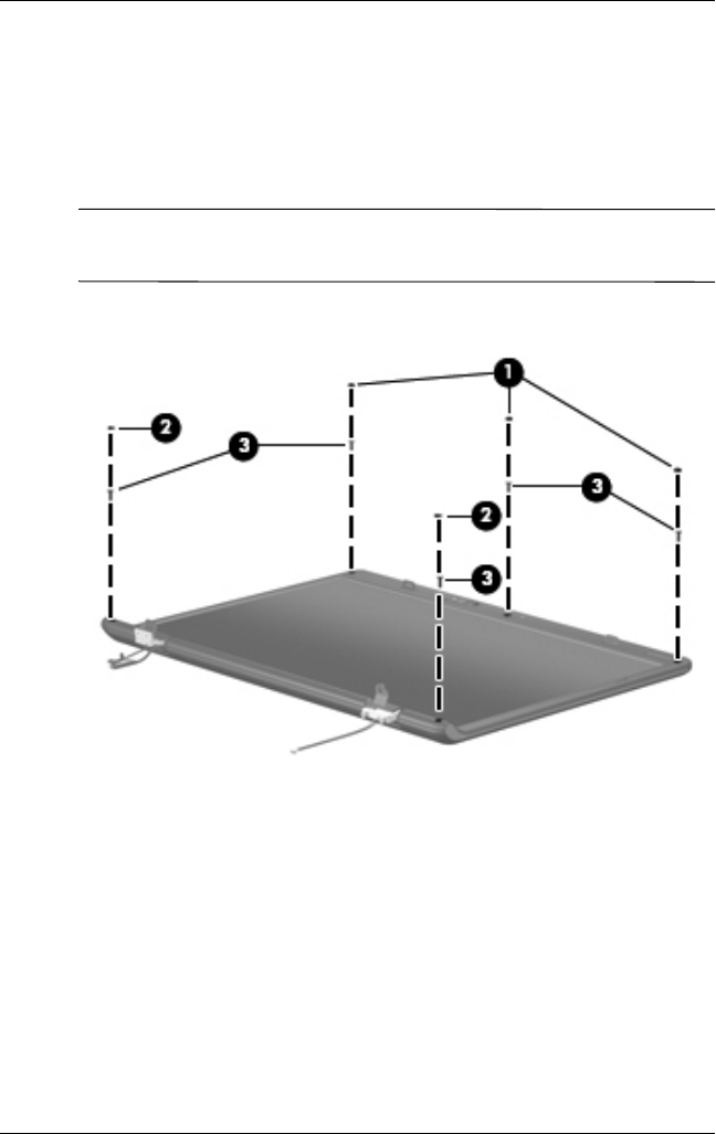
12. Remove the following:
1 Three rubber screw covers on the display bezel top edge
2 Two rubber screw covers on the display bezel bottom edge
3 Five Phillips PM2.5×8.0 screws
✎
The display rubber screw covers are included in the Display
Screw Kit, spare part number 432967-001.
Removing the Display Bezel Screws