


5–70 Maintenance and Service Guide
Removal and Replacement Procedures
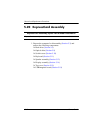
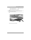
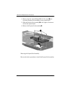
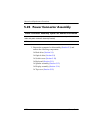
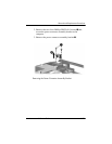
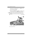
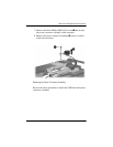
5.23 Power Connector Assembly
1. Prepare the computer for disassembly (Section 5.3) and
remove the following components:
❏ Hard drive (Section 5.4)
❏ Optical drive (Section 5.9)
❏ Switch cover (Section 5.10)
❏ Keyboard (Section 5.11)
❏ Speaker assembly (Section 5.12)
❏ Display assembly (Section 5.14)
❏ Top cover (Section 5.15)
Power Connector Assembly Spare Part Number Information
Power connector assembly (includes power connector assembly
cable and power connector assembly bracket)
432985-001
USB board 432989-001