


Installing the switch 18
Installing the switch
In this section
Preparing for installation ......................................................................................................................... 18
Planning the switch configuration ............................................................................................................. 18
Installing the switch ................................................................................................................................ 21
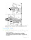
Accessing the switch............................................................................................................................... 22
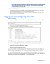
Logging on and configuring the switch...................................................................................................... 23
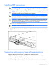
Installing XFP transceivers........................................................................................................................ 24
Supporting software and special considerations......................................................................................... 24
Preparing for installation
IMPORTANT: Before installing the switch, make a record of the MAC address (printed on the
MAC address label attached to the switch). This address is needed when configuring the
switch.
Planning the switch configuration
The switch ships with a default configuration in which all downlink and uplink ports are enabled and
assigned a default VLAN with a VID equal to 1. This default configuration simplifies the initial setup by
allowing use of a single uplink cable (from any external Ethernet connector) to connect the server blade
enclosure to the network. Assess the particular server environment to determine any requirements for other
considerations.
The switch does not affect or determine NIC numeration and the associated mapping of NIC interfaces to
switch ports. The numbering of the NICs on the server (for example, NIC 1, NIC 2, NIC 3) is determined
by the server type, the server operating system, and which NICs are enabled on the server.
NOTE: Port 18 is reserved for connection to the Onboard Administrator module for switch
management. This allows a user to enable the functionality of future firmware upgrade
releases.
The Onboard Administrator module controls all port enabling. Enabling is based on matching ports
between the server and the interconnect bay. Before power up, the Onboard Administrator module
verifies that the server NIC option matches the switch bay that is selected and enables all ports for the
NICs installed.
For detailed port mapping information, see the HP BladeSystem enclosure installation poster or the HP
BladeSystem enclosure setup and installation guide on the HP website
(http://www.hp.com/go/bladesystem/documentation
).
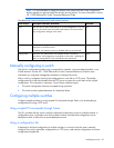
Default settings
When planning the configuration, consider the default settings for these parameters: