


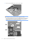
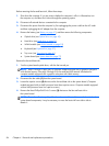
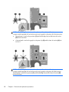
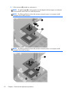

NOTE: The following illustration shows the replacement thermal material locations on a
computer model equipped with an Intel processor and a graphics subsystem with discrete memory.
●
Thermal paste is used on the processor (1) and Northbridge chip and the heat sink section
(2) that services them
●
A thermal pad is used on the graphics subsystem chip (3) and the heat sink section (4) that
services it
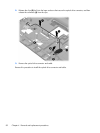
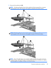
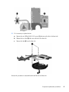
NOTE: The following illustration shows the replacement thermal material locations on a
computer model equipped with an Intel processor and a graphics subsystem with UMA memory.
Thermal paste is used on the processor (1) and Northbridge chip and the heat sink section (2)
that services them.
88 Chapter 4 Removal and replacement procedures