


14
• Specify the IP-based management networks that are allowed to access each switch.
• Set a user interface idle time-out period and disable web-based and Telnet access.
• Enable a secure shell (SSH) session to the CLI interface.
• Modify default Telnet and HTTP server socket port numbers.
Additional switch security measures include:
• RADIUS RFC 2865 to provide user authentication and authorization.
• Port-based IEEE 802.1Q tagged VLANs for server grouping and data isolation.
• Secure copy protocol (SCP) to securely upload and download the switch configuration file.
• The ability place the switch in an unique “safe mode” configuration with the included example
templates.
When users insert a new or replacement GbE2 Interconnect Switch into a production/real-time
environment, they must ensure that the GbE2 Interconnect Switch configuration is compatible with the
production network. Because the factory default configuration of a new interconnect switch may not
be same as the production configuration, inserting the new switch may compromise the security
aspects and VLAN isolation used by the production network.
A new or replacement interconnect switch can be installed in "safe mode" to address network
compatibility and security issues and to allow the administrator to configure the switch and finalize
switch deployment on the production network. Network compatibility includes spanning tree protocol
loop avoidance. Security issues include items such as VLAN isolation, user-passwords, and SNMP
read-write community strings. The GbE2 Interconnect Switch includes an example safe mode template
configuration file as a basis to create an appropriate safe mode configuration. The administrator can
simply download a final configuration template with the safe mode configuration to deploy the GbE2
Interconnect Switch in the production environment.
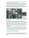
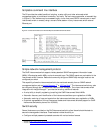
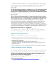
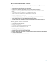
Serviceability and diagnostics
The GbE2 Interconnect Switch has several serviceability features such as the front-mounted, hot-
swappable interconnect switch blade, the front panel RS-232 port, Gigabit Ethernet ports, and a
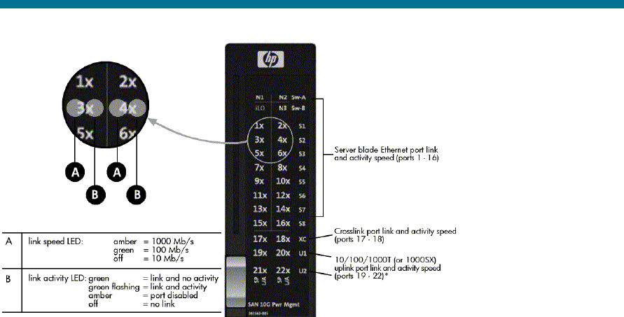
power re-set switch. The interconnect switch also has system status LEDs and a LED annunciation panel
that displays the link speed and activity status for each port (Figure 10).
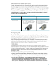
Figure 10. Front port LED panel for ProLiant BL p-Class GbE2 Interconnect Switch
*Uplink ports on the p-Class C-GbE2 Interconnect Kit are 10/100/1000T.
Uplink ports on the p-Class F-GbE2 Interconnect Kit are 1000SX.