


NUMA configuration 68
Advanced configuration example
This example server has four NUMA nodes with eight hyper-threaded cores per node (16 logical processors
per node, a total of 64 logical processors in the system). This system also uses the expansion configuration
and has 11 PCIe expansion slots. During system boot, the system BIOS assigns PCIe slots 1-6 to NUMA node
2 and PCIe slots 7-11 to NUMA node 0. NUMA nodes 1 and 3 have no assigned PCIe slots. This
configuration creates a load balancing problem in the system when IO Accelerator devices are under heavy
traffic. During these periods of high use, half of the processors in the system sit idle while the other half of the
processors are 100% utilized, thus limiting the throughput of the IO Accelerator devices.
To avoid this situation, you must manually configure the affinity of the IO Accelerator devices using the
FIO_AFFINITY configuration parameter to distribute the work load across all NUMA nodes. This
parameter overrides the default behavior of the IO Accelerator driver. For more information about the
FIO_AFFINITY configuration parameter, refer to the syntax explanation below.
Syntax:
The following is an example of how to configure 10 HP IO Accelerator ioDrive Duo devices (each with two
IO Accelerator devices) in a HP DL580 G7 system manually as described in the preceding paragraphs. Slot
1 is a Generation 1 PCIe slot, so it is not compatible with an ioDrive Duo device. Therefore you can fill slots
2-11 with ioDrive Duo devices. Because each ioDrive Duo device has two IO Accelerator devices, each
ioDrive Duo devices has two device numbers (one for each IO Accelerator device). Each slot has two device
numbers.
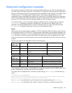
The following tables list the default BIOS NUMA node assignments.
BIOS assigned
NUMA node
PCIe slots FCT device numbers Processor Affinity
0
7-11 8,9,13,14,18,19,23,24,28,29 All processors in the node
1
None None None
2
2-6 135,136,140,141,145,146,150,151,
155,156
All processors in the node
3
None None None
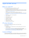
Assigned
NUMA node
PCIe slots FCT device numbers Processor Affinity
0
7-9 8,9,13,14,18,19 All processors in the node (no hex mask)
1
10-11 23,24,28,29 All processors in the node (no hex mask)
2
2-3 135,136,140,141 All processors in the node (no hex mask)
3
4-6 145,146,150,151,155,156 All processors in the node (no hex mask)
In this example, the BIOS creates a load imbalance by assigning the cards to only two NUMA nodes in the
system. To balance the work load, enter the following settings:
To configure the IO Accelerator driver with these override settings, run fio-config with the following
string:
fio-config -p FIO_AFFINITY
8,n0;9,n0;13,n0;14,n0;18,n0;19,n0;23,n1;24,n1;28,n1;29,n1;135,n2;136,n2;140,
n2;141,n2;145,n3;146,n3;150,n3;151,n3;155,n3;156,n3
No <hex mask> was stipulated for any of the devices in this example (making each <affinity
specification> a couplet rather than a triplet). Therefore, each device is shared among all of the