


ADDITIONAL UPS FEATURES
HP T750 G2, HP T750J, HP T1000 G3, HP T1000J, HP T1500 G3, and HP T1500J UPS Models User Guide S 505922-002
15
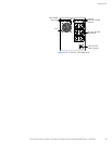
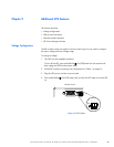
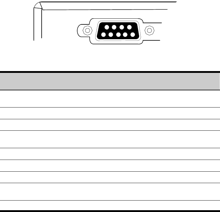
Serial Port
To establish communication between the UPS and a computer, connect your computer
to the UPS serial port using the supplied communication cable.
When the communication cable is installed, HP Power Manager software can exchange
data with the UPS. The software polls the UPS for detailed information on the status of
the power environment. If a power emergency occurs, the software initiates the saving
of all data and an orderly shutdown of the equipment.
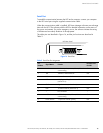
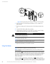
The cable pins are identified in Figure 16, and the pin functions are described in
Table 2.
3
8
7
9
1
6
245
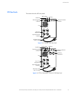
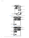
UPS Rear Panel
Figure 16 Serial Port
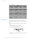
Table 2 Serial Port Pin Assignment
Pin
Number
Signal Name Function
Direction from
the UPS
1 Low Batt Low battery relay contact; 20 mA, 30 Vdc
contact rating
Out
2 TxD Transmit to external device Out
3 RxD Receive from external device In
4 DTR PnP (Plug and Play) from external device
(tied to Pin 6)
In
5 GND Signal common (tied to chassis) —
6 DSR To external device (tied to Pin 4) Out
7 — No connection —
8 AC Fail AC fail relay contact; 20 mA, 30 Vdc
contact rating
Out
9 Power Source +V (8 to 24 volts DC power) Out