


Display assembly
NOTE: Each display assembly spare part kit includes 1 webcam, 1 microphone, 1 speaker box, and
2 WLAN antenna transceivers/cables; WWAN is optional.
NOTE: 10.1-inch display assembly components are not sold separately for the HP Mini 1000. The
complete display assembly is available as spare part number 509696-001 for the red-colored
HP Mini 1000 or 507312-001 for all other models of the HP Mini 1000.
NOTE: 10.2-inch display assembly components are not sold separately. The complete display
assembly is available as spare part number 512140-001 for the red-colored HP Mini 1000, 507310-001
for all other models of the HP Mini 1000, or 512143-001 for the Compaq Mini 700.
Description Spare part number
8.9-inch, WSVGA, BrightView (HP Mini 1000) 507309-001
8.9-inch WSVGA BrightView (Compaq Mini 700) 508638-001
10.1-inch standard-definition AntiGlare (HP Mini 1000) 507312-001
10.1-inch standard-definition AntiGlare (red-colored HP Mini 1000) 509696-001
10.1-inch standard-definition AntiGlare (Compaq Mini 700) 509697-001
10.2-inch WSVGA AntiGlare (HP Mini 1000) 507310-001
10.2-inch WSVGA AntiGlare (red-colored HP Mini 1000) 512140-001
10.2-inch WSVGA AntiGlare (Compaq Mini 700) 512143-001
See Display assembly components on page 17 for more spare part information.
Before removing the display assembly, follow these steps:
1. Shut down the device. If you are unsure whether the device is off or in Hibernation, turn the device
on, and then shut it down through the operating system.
2. Disconnect all external devices connected to the device.
3. Disconnect the power from the device by first unplugging the power cord from the AC outlet and
then unplugging the AC adapter from the device.
4. Remove the battery (see
Battery on page 37).
5. Remove the following components:
a. Keyboard (see
Keyboard on page 40)
b. Hard drive or solid-state drive (see
Mass storage devices on page 42)
c. Top cover (see
Top cover on page 45)
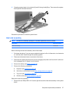
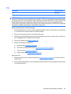
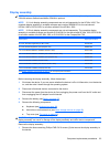
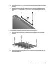
CAUTION: Support the display assembly when removing the following screws. Failure to support the
display assembly can result in damage to the display assembly and other device components.
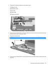
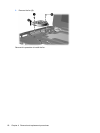
Remove the display assembly:
1. Remove the three remaining Phillips PM2.5×5.0 screws (1) that secure the display assembly to
the device.
Component replacement procedures 63