


301CSI Section 16160
Siemens Electrical Products and Systems
Specification Guide
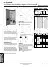
AC Controls
15
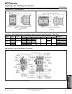
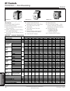
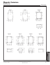
Dimensions / Wiring Diagrams
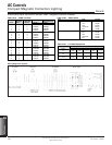
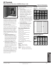
Magnetic Contactors
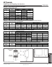
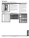
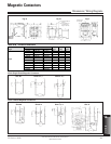
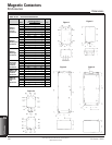
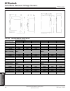
Table 15.29 Contactor Dimensions
Half
Size
NEMA
Size
Open
2
2
1
/2
3
3
1
/2
4
4
1
/2
5
6
Type
00
0–1
1
3
/4
Figure
AB C
Dimensions in Inches (mm)
1b
1b
1b
1b
1b
1b
2
2
2
2
1a
3.75 (95) 5.50 (140)
4.31 (109)
4.75 (121)
4.31 (109)
4.75 (121)
4.88 (124) 4.50 (114)
6.13 (156) 5.50 (140)
17.38 (441) —
22.50 (572) —
4.88 (124) 4.25 (110)
6.13 (156) 5.50 (140)
7.81 (198) 5.50 (140)
17.38 (441) —
3.19 (81)
3.75 (95)
3.75 (95)
4.00 (102)
4.00 (102)
5.06 (129)
5.06 (129)
5.75 (146)
7.88 (200)
7.88 (200)
10.00 (254)
Size 00 Sizes 0–1
3
/4
Size 00 Size 0–4 Size 4
1
/2, 5 Size 6
Fig 1a Fig 1b Fig 2
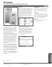
2 Pole Single Phase Magnetic Contactors
3 Pole 3 Phase Magnetic Contactors
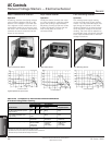
Optional
Electrical
Contacts
B1 Front Mounted Aux
Contact
B2 Aux Contact and 1
Aux Power Pole
Right or Left Side
Side Mounted
Aux Contact
Sizes 2–3
1
/2