


5–62 Maintenance and Service Guide
Removal and Replacement Procedures
g. RTC battery (Section 5.14)
h. Switch cover (Section 5.17)
i. Display assembly (Section 5.18)
j. Top cover (Section 5.19)
k. Speaker (Section 5.20)
l. Microphone (Section 5.21)
m. USB/audio board (Section 5.23)
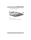
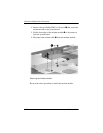
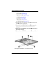
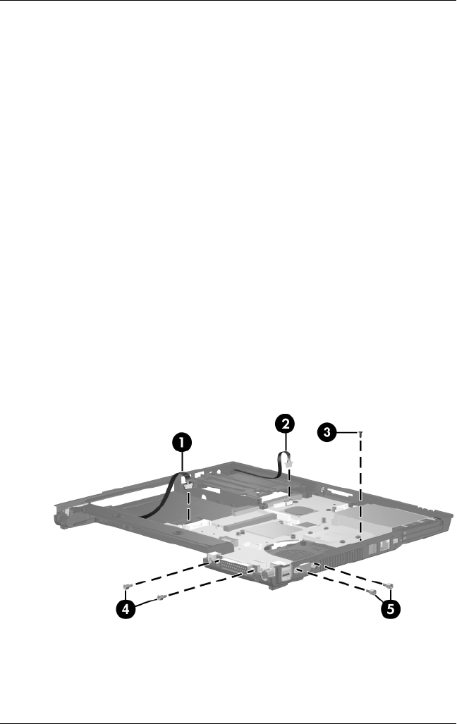
2. Disconnect the serial connector cable 1 and the Bluetooth
cable 2 from the system board.
3. Remove the Torx8 T8M2.5×4.0 screw 3 that secures the
system board to the base enclosure next to the RJ-11
connector.
4. Remove the two HM5.0×9.0 screw locks 4 on each side of
the parallel connector.
5. Remove the two HM5.0×9.0 screw locks 5 on each side of
the external monitor connectors.
Removing the System Board Screws and Screw Locks