


Removal and Replacement Procedures
Maintenance and Service Guide 5–65
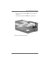
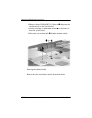
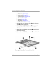
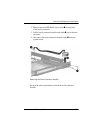
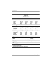
2. Remove the two HM5.0×9.0 screw locks 1 on each side
of the serial connector.
3. Lift the serial connector module and cable 2 out of the base
enclosure.
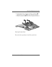
4. Disconnect the serial connector module cable 3 from the
system board.
Removing the Serial Connector Module
Reverse the above procedures to install the serial connector
module.