


Daytona Twin Tec LLC, 933 Beville Road, Suite 101-H, S. Daytona, FL 32119 TCFI Log
(386) 304-0700 www.daytona-twintec.com
3/2007
Page 3
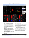
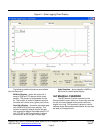
Figure 1 – Real Time Engine Data Display
AFR – the air/fuel ratio bar graph has dual
pointers. The yellow pointer on the left side is
the air/fuel ratio command (from AFR table). The
white pointer on the right side is the actual
air/fuel ratio based on the exhaust gas oxygen
sensor reading. Note that the value will remain
near 10 until the sensor has warmed up. Front
and rear cylinder AFR values are displayed for
TCFI IID units.
BLM – block learn multiplier (main fuel table
correction factor based on exhaust gas oxygen
sensor feedback, shown as percent value from
75-125%). Front and rear cylinder BLM values
are displayed for TCFI IID units.
FRONT INJ PW, REAR INJ PW – injector pulse
width in milliseconds
FRONT ADV, REAR ADV – ignition advance in
degrees BTDC
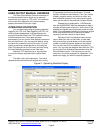
IDLE TPS DISPLAY
You can check the idle TPS adjustment by using
the View Idle TPS command on the View menu. Turn
the run/stop switch on, but do not start the engine
when using this function. Idle TPS volts are displayed
on the TPS bar graph gauge. All other instrument
values will appear as zero.
With the throttle fully closed, verify that the
gauge display is between .30 to .80 volts for TCFI IID
units or between .35 to .45 volts for all other TCFI and
TCFI II units. If the value is outside this range, you will
have to adjust the TPS sensor. For optimum
performance, adjust the TPS sensor to .40 volts.