Chapter 3
Page 10 of 16
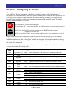
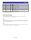
C005
Terminal 5
Function
255 (no) No Function – SJ200 (SJ700)
C006
Terminal 6
Function
18 [RS] Reset
C007
Terminal 7
Function
no [NO] No Function – SJ700 only
C008
Terminal 8
Function
no [NO] No Function – SJ700 only
C011 thru
C016[DN]
Terminal Active
State
00
All inputs should be configured for N.O. (normally open = active on)
operation (Note 2)
C102
Reset function
selection
2
Makes the RESET [RS] input terminal (input 6) active only when the inverter
is in the fault state. In this way, the pendant DOWN pushbutton can also
used to reset an inverter fault.
Note 1: Actual setting is dependent on inverter capacity and your design requirements
Note 2: C011 to C018 in the case of SJ700 series
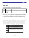
Other Required Settings
The following were previously noted in the Installation and Wiring chapter, but are important and bear
repeating. Make sure the following steps were performed.
SJ200
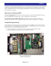
The SR/SK DIP switch next to the input terminal strip must be in the default “SR” position for proper operation
of the 115VIF-3 interface board. Verify that it is in the correct position. Confirm the correct setting of B091 for
load-brake vs. non-load-brake applications.
SJ700
Confirm that the silver source/sink jumper bar is between PLC and CM1, as explained in Chapter 2. Confirm the
correct setting of B091 for load-brake vs. non-load-brake applications.


