


Chapter 2
Page 7 of 16
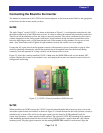
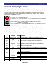
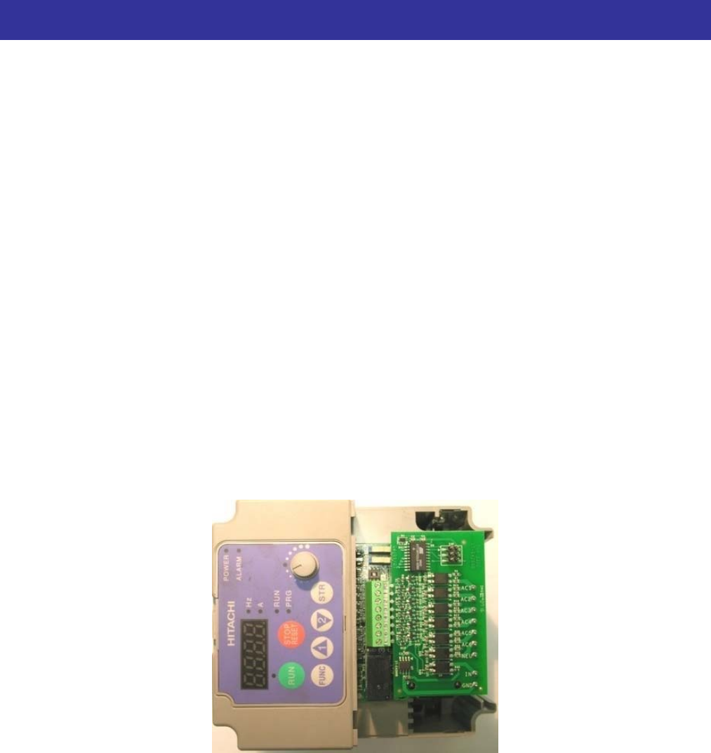
Figure 2-3, 115VIF-3 Correctly Installed in SJ200 Inverter
J700
losest to
Connecting the Board to the Inverter
The method of connection of the 115VIF to the inverter depends on the inverter model. Refer to the appropriate
section below for the inverter model you have.
SJ200
The eight “fingers” on the 115VIF-3, as shown at the bottom of Figure 2-1, are designed to mate directly with
the input terminal strip of the SJ200 series inverter. It is best to remove the terminal strip from the inverter first.
Then loosen all the terminals to allow the fingers to be easily inserted. The correct orientation for the board is
with the integrated circuits facing upward, and the AC input terminals facing downward toward the inverter.
Insert the eight fingers until you feel them hit that back of the terminal wiring chambers. Do not try to force
them – they should enter easily. Tighten all eight terminals securely. Be careful to not over-tighten.
Connect the AC signal wires from the pendant controls to the terminal as shown in the table on page 6. After
carefully tightening all terminals, reinstall the terminal strip with attached board into the inverter mating
connector, and route pendant AC wiring carefully out the bottom of the inverter.
Figure 2-3 shows the correctly installed 115VIF-3. Make sure the SR/SK DIP switch is in the default “SR”
position. Replace the inverter lower terminal cover, and energize the inverter and external control circuits for
configuration and testing.
S
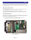
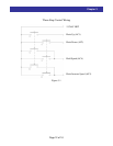
When installed in an SJ700 inverter, the 115VIF-3 must be mounted behind the inverter top front cover in the
area where option boards are installed, as shown in Figure 2-4. Install the board in the lower position (c
terminal strip) as shown. This will leave the upper option slot free should a SJ-FB feedback board (for
closed-loop operation), or other option board be required. The optional 115VIF-KIT mounting kit is required
when mounting the interface board in these inverter series. The kit includes a pigtail cable and a M3 x 8mm
mounting screw. Plug the pigtail connector into the mating OUTPUTS2 connector on the board. Align the