


Chapter 3
Page 9 of 16
Chapter 3 – Configuring the Inverter
The configuration of inverter parameters will depend on the specific functionality and performance required for
your application. The basic functionality of the board is designed to interface with a two pushbutton,
two-position (two-speed) momentary contact type pendant commonly used for crane and hoist applications. This
is the basis for the descriptions of the functions of the board presented in this manual. The setup in the table
below will result in infinitely variable speed between the programmed MIN and MAX speeds. The defined
functions of the pushbuttons are as follows:
UP
DOWN
UP, first detent: UP – accelerate to minimum speed
UP, second detent: UP – increase speed while held, up to MAX speed (or go to second speed, see page 10)
DOWN, first detent: DOWN – accelerate to minimum speed (RESET fault when inverter is
STOPPED and in a fault state)
DOWN, second detent: DOWN – increase speed, up to MAX speed (or go to second speed, see page 10)
Pushing either the UP or DOWN pushbutton to the first position causes the inverter to go to the minimum
configured speed in that direction. Pushing that button further to its second position will cause speed to increase
in that direction. Releasing back to first position will hold that last speed. Releasing the pushbutton all the way
will cause the inverter to come to a stop. If that button is re-pressed to the first position before stop is reached,
that speed will be maintained.
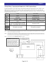
In order to achieve this basic functionality, certain parameters must be set differently from factory default
values, as described in the following table.
Parameter
Code
Function Setting Comment
F002 Acceleration Time Note 1 Set a value between 1 and 3600 seconds, depending on application
F003
Deceleration
Time
Note 1 Set a value between 1 and 3600 seconds, depending on application
A001
Frequency
Command
02 Tells the inverter to read speed reference from internal register
A002 Run Command 01 Tells the inverter to take the RUN command from the control terminals
A004
Maximum
Frequency
Note 1
Depending on the motor limits and application requirements, set the
appropriate value
A061
Upper Frequency
Limit
Note 1 Usually the same value as A004
A062
Lower Frequency
Limit
Note 1
Lowest speed for continuous operation (MIN speed), usually 6 to 10 Hz or
so. This is the speed that will be commanded at the first pushbutton position.
00 For Non-Load Brake Hoist, or for traverse applications: 00 (factory default)
Stop Mode
Selection
B091
01 For Load Brake Hoist applications: 01 (free-run or coast to stop)
00 SJ200 = [FW] Forward run
no SJ700 Open Loop = [NO] No function
Terminal 1
Function
C001
56 SJ700 Closed Loop = [MI1]
01 SJ200&SJ700 Open Loop = [RV] Reverse run
Terminal 2
Function
C002
57 SJ700 Closed Loop = [MI2]
Terminal 3
Function
C003 27 [UP] Accelerate speed input
Terminal 4
Function
C004
28 [DN] Decelerate speed input