


Chapter 2
Page 8 of 16
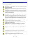
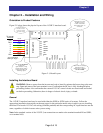
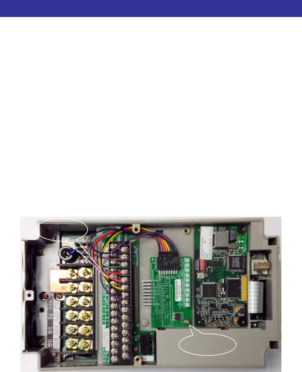
mounting hole in the board with the threaded insert as shown in the figure. Secure the board to the inverter wi
the M3 screw supplied with the mounting kit. Connect the pigtail leads to the I/O terminal strip of the SJ700
inverter. Connect the leads one b
th
y one to intelligent input terminals on the inverter following the color coding
own in Figure 2-1 on page 5.
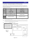
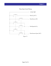
pen-Loop vs. Closed-Loop SJ700
terminal. In this case
ere is no connection to intelligent input 1, which is configured for no function [NO].
telligent input terminal 1, which is configured for [MI1] function. Refer to parameter tables in Chapter 3.
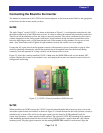
inking/Sourcing Input Set-up
n. To change the logic setting, locate the small
etal jumper bar on the intelligent input terminal strip. Then:
and PLC terminal.
2) Reinstall the jumper between the PLC terminal and the CM1 terminal
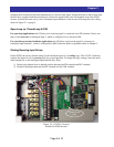
Fi y
Installed in SJ700 Inverter
sh
O
For open-loop applications: the UP (blue) wire from the pigtail is connected to the FW
th
For closed-loop (encoder feedback) applications: the UP (blue) wire from the pigtail is connected to
in
S
On the SJ700, the factory default setting for the intelligent inputs is for sinking logic. The 115VIF-3 interface
requires the inputs be set for sourcing logic for proper operatio
m
1) Remove the jumper from its default position between the P24 terminal
S e
Jumper
ink/Sourc
(1) M
screw
3 x 8 mm
gure 2-4, 115VIF-3 Correctl