


5K320 SATA OEM Specification
- 47 -
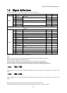
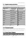
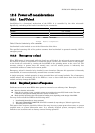
11.1 Register naming convention
This specification uses the same naming conventions for the Command Block Registers as the
ATA8-ACS standard. However, the register naming convention is different from that uses in the
Serial ATA 2.6 specification. The following table defines the corresponding of the register names
used in this specification with those used in the Serial ATA 2.6 specification.
Serial ATA register
name
Register name in this
specification when
writing registers
Register name in this
specification when
reading registers
Features Feature current
Features (exp) Feature previous
Sector count Sector count current Sector count HOB=0
Sector count (exp) Sector count previous Sector count HOB=1
LBA low LBA low current LBA low HOB=0
LBA low (exp) LBA low previous LBA low HOB=1
LBA mid LBA mid current LBA mid HOB=0
LBA mid (exp) LBA mid previous LBA mid HOB=1
LBA high LBA high current LBA mid HOB=0
LBA high (exp) LBA high previous LBA mid HOB=1
Device Device Device
Command Command N/A
Control Device Control N/A
Status N/A Status
Error N/A Error
Table 24 Register naming convention and correspondence
11.2 Command register
This register contains the command code being sent to the device. Command execution begins
immediately after this register is written. The command set is shown in “Table 40 Command set” on
page 75.
Al
l other registers required for the command must be set up before writing the Command Register.
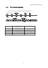
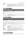
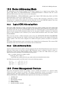
11.3 Device Control Register
Device Control Register
7 6 5 4 3 2 1 0
- - - - 1 SRST -IEN 0
Table 25 Device Control Register