


Drawing No. Sheet No. Revision
K6610091 31/43 2005/2/23
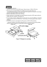
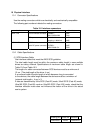
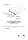
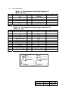
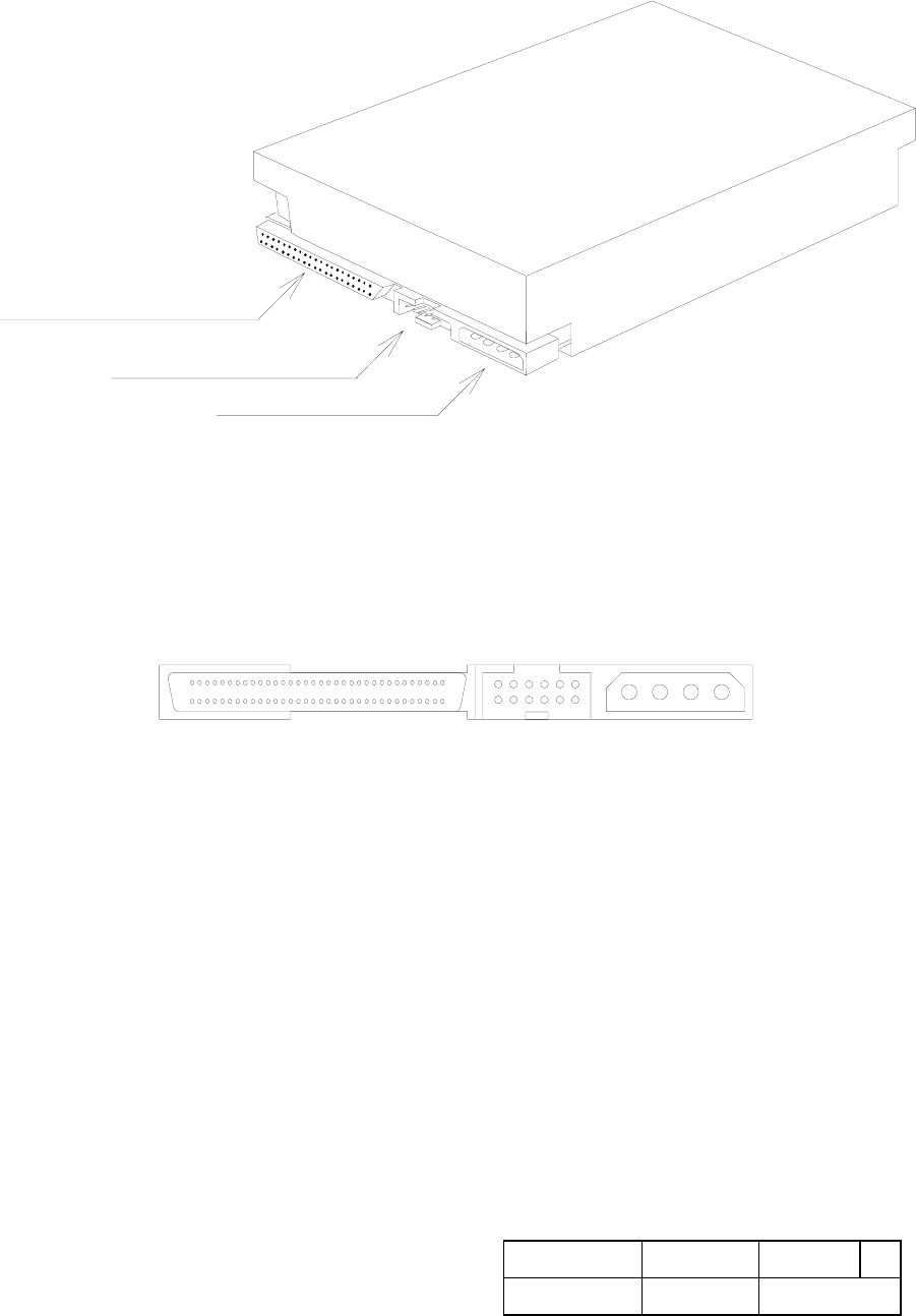
10.3 Connector Layout
WIDE LVD drive
C1
SCSI Bus Connector
C4
Auxiliary Connector
C2
Power Connector
Figure 10.1 Connector Layout (WIDE LVD drive)
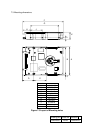
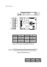
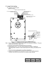
C1
4321
68
1
34
2
12
1
11
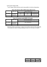
C2-1 : 12V
C2-2 : GND (12V Return)
C2-3 : GND (5V Return)
C2-4 : 5V
35
C4 C2
Figure 10.2 Connector view
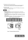
Note: The SCSI ID setting is to be set via the C3 connector (not by C4) normally.
In case the SCSI ID setting is done by remote switch via the C4 connector and
remote cable, remove all Jumper Sockets from the C3 connector to avoid SCSI
ID control conflicts.