


Drawing No. Sheet No. Revision
K6610091 38/43 2005/2/23
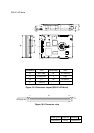
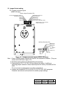
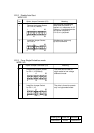
12 Jumper Socket setting
12.1 Jumper connector layout
WIDE LVD drive
Reserved (4)
Reserved (6)
Auxiliary Connector (C4)
2
1
ID0 (1)
ID1 (3)
ID2
(5)
ID3 (7)
GND (10)
N.C. (9)
5V (11)
Write Protect (12)
LED (8)
Reserved (2)
12
11
Option Jumper Connector (C3)
1
2
23
24
Force Single-Ended bus mode (11)
Disable Auto Start (9)
ID2 (3)
ID1 (5)
ID0 (7)
ID3 (1)
Enable Delayed Start (13)
Write Protect (15)
LED(with 0ohm) (21)
Reserved (19)
Term. Power to SCSI Bus (23,24)
Reserved (17)
5V(with 150ohm) (22)
GND (2,4,6,8,10,12,14,16,18,20)
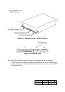
Figure 12.1 Jumper connector layout (WIDE LVD drive)
Note 1. Green or White jumper sockets are used for the customer’s selection. (They are
shown with thick lines in figure 13.1)
2. Shaded jumper sockets are default setting at the factory.
3. Reserved pins (C3-17,19; C4-2,4,6) are used at the factory. Installing or
removing jumper sockets on these reserved pins will void any warranties of the
HDD.
Do not connect an assigned pin to another assigned pin.
4. Jumpers are installed at C3-2,4 & 6,8 & 10,12 & 14,16 & 18,20 as spares.
Customer can remove and use them for another jumper settings.