


SJ100/L100 / PID / 10
3-2 Summary of Parameters for PID Control
On the SJ100/L100 series inverters, the same function numbers are used for both frequency control
mode and PID control mode. The function name for each function is based on frequency control mode,
which is normally used for general application. Therefore, some functions have misleading explanations in
the instruction manual.
To avoid confusion, please find in below Table 3-1 the explanation of function names for frequency
control mode and PID control mode.
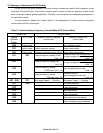
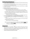
Table 3-1 Relation between Frequency Control Mode & PID Control Mode
Function No. Function name
Integral
Operator
Display
DOP, DRW
Contents in case of Frequency
control mode
Contents in case of PID
control mode
D04
Monitor mode
- PID Feedback monitor
F01
Monitor mode
Output frequency monitor Target value monitor
A01
Monitor mode
Frequency command origin setting Target value origin setting
A11 F31
External frequency setting START
(Unit : Hz)
Feedback value input corresponding %
for lower acceptance level
(Unit : %)
A12
External frequency setting END
(unit : Hz)
Feedback value input corresponding %
for upper acceptance level
(Unit : %)
A13
External frequency setting
START rate (Unit : Hz)
Feedback value of
lower acceptance level input
(Unit : %)
A14
External frequency setting
END rate (unit : Hz)
Feedback value of
upper acceptance level input
(Unit : %)
A21 - A35 F11
Multi-stage Speed 1 - 15 setting Multi-stage Target 1 - 15 setting
A71 F39
- PID mode selection
A72
P-gain adjustment
A73
I-gain adjustment
A74
D-gain adjustment
A75
Scale conversion ratio setting
A76
Origin of feedback signal selection