


SJ100/L100 / PID / 12
(3) Scale Conversion Factor Setting
Set this factor according to your application, e.g. flow, pressure, temperature and so on. For a detailed
explanation, please refer to item (6) on page 9.
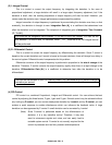
(4) Target Input by Digital Input Signal
Please refer to the following when changing the target with the digital input signal (4 bit max.).
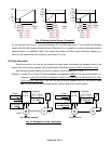
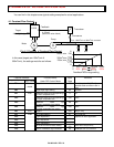
(a) Input terminal assignment
L100 series inverters have five intelligent input terminals. The SJ100 series have six. Assign “CF1”,
“CF2”, “CF3” and “CF4” to 4 of the intelligent input terminals. This assignment is done with function
numbers C01 to C05 (or C06 for SJ100), which correspond to terminals 1 to 5 (or 6) on the I/O
terminal.
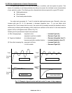
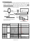
(b) Setting each target value
Next, set the required number of targets (up to 16 targets maximum) according to the following table
(Table 3-3). Set them using functions A21 to A35 which correspond to target 0 to 15. A20 and F01
correspond to a target 0. Please note that in case a scale conversion ratio is set, you should set those
targets as converted value according to this ratio.
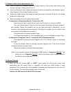
Table 3-3 Multi-stage Target Input (1 : ON, 0 : OFF)
No. CF4 CF3 CF2 CF1 Referred Target number (Function number to be inputted)
1 0 0 0 0
Target 0 (A20 or F01)
2 0 0 0 1
Target 1 (A21)
3 0 0 1 0
Target 2 (A22)
4 0 0 1 1
Target 3 (A23)
5 0 1 0 0
Target 4 (A24)
6 0 1 0 1
Target 5 (A25)
7 0 1 1 0
Target 6 (A26)
8 0 1 1 1
Target 7 (A27)
9 1 0 0 0
Target 8 (A28)
10 1 0 0 1
Target 9 (A29)
11 1 0 1 0
Target 10 (A30)
12 1 0 1 1
Target 11 (A31)
13 1 1 0 0
Target 12 (A32)
14 1 1 0 1
Target 13 (A33)
15 1 1 1 0
Target 14 (A34)
16 1 1 1 1
Target 15 (A35)
Note: If you need only 4 targets, you would only use CF1 and CF2.
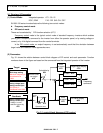
(5) PID Mode Selection
Set PID mode selection A71 to “01”. You can also set this function first.