


SJ100/L100 / PID / 7
3. HOW TO USE
3-1 Structure & Parameters
(1) Control Mode Integrated operator A71 : 00 / 01
DOP, DRW F43 : PID SW ON / OFF
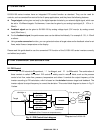
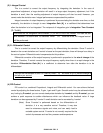
SJ100/L100 series inverters feature the following two control modes:
l Frequency control mode
l PID control mode
These can be selected by “PID function selection (A71)”.
Frequency control mode is the typical control mode of standard frequency inverters which enables
you to give a frequency command to the inverter from either the operator panel, or by analog voltage or
current, or by 4 bit digital command from the control terminals.
In the PID control mode, an output frequency is set automatically such that the deviation between
target value and feedback value approaches zero.
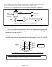
(2) Parameters
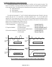
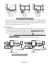
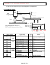
Fig. 3-1 shows the relation between control block diagram of PID control and each parameter. Function
numbers shown in the figure are based on the commands from the integrated operator of the inverter.
+
+
+
Selectable by
A01
Frequency
command
I Gain : A73
P Gain : A72
D Gain : A74
Operator
Multi stage setting
Maximum frequency is
considered to be
100%
Pot-meter
Analog voltage input
Analog current input
10V (20mA) is
considered to be 100%
Fig. 3-1 control block diagram of PID control
Scale
conversion
A75
Target value display
: F01
Target
Analog voltage input
Analog current input
Voltage / current
selection is done by
A76
Feedback
100%
A12
A11
0
A14
A13
Operation area
FB value display :
d04
Scale
conversion
A75
Reverse scale
conversion
A75
-1