


M-510324 301C User Manual 21
7/10 Honeywell
Getting Started
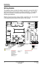
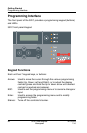
Programming Interface
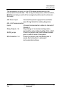
LED Definitions
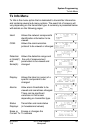
The controller is equipped with 7 LEDs that provide a status for each
function related to that indicator:
Alarm A: A blinking red light indicates that an event has been
activated. A constant red light indicates that one or more
transmitters has reached Alarm A or Alarm 1.
Alarm B When the red indicator is on, one or more transmitters has
reached Alarm B or Alarm 2.
Alarm C When the red indicator is on, one or more transmitters has
reached Alarm C.
Power: Green indicates that the unit is powered up and functional
Fault: When the amber LED is on, it indicates a fault (i.e. a
communication, maintenance or device problem)
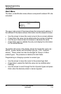
Tx: When the amber LED is blinking, it indicates that the
controller is sending information or requests on the
communication channel.
Rx: When the green LED is blinking, it indicates that the
controller is receiving information.
Each of these functions is linked to parameters programmed in the
control unit, which we will discuss in the following section.
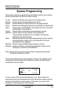
System Operation
The system operates in four different modes that allow it to use,
analyze, debug, and simulate the actions that the system can perform.
These modes are: Normal, Single Tx, Debug and Simulate. The default
system operation mode is Normal. The other modes are available
through the Tests menu (option 8 from the Main Menu).
Note: Systems services may be disrupted by some menu operations.