


SUB SERIES INTERVAL DATA RECORDERS
62-0342—01 2
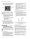
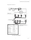
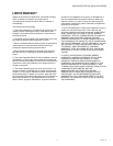
3. Modular Jacks & Screw-Type Connectors (SUBIDR-16
ONLY): Supplied with 8 modular jacks and 8 screw-type
connectors. Used with a mixture of Honeywell and third-
party meters. (Requires external power supply.)
Fig. 3. IDR with both types of connectors.
MECHANICAL INSTALLATION
IMPORTANT:
THE INTERNAL CIRCUITS OF THE IDR CAN BE
DAMAGED BY ELECTROSTATIC DISCHARGE.
BEFORE REACHING INSIDE THE ENCLOSURE,
DISCHARGE YOURSELF BY TOUCHING AN
EARTH-GROUNDED OBJECT.
ACCIDENTAL DISCHARGE OF STATIC ELECTRIC-
ITY ONTO THE CIRCUIT BOARD CAN RESULT IN:
- LOSS OF STORED DATA
- A SYSTEM LOCK-UP
- PERMANENT DAMAGE TO THE IDR
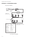
The IDR is available in two types of enclosure systems:
1. Stand-Alone IDR (Standard Configuration)
The stand-alone IDR configuration consists of a single
IDR unit. The enclosure should be mounted using the
mounting flanges located at the top and bottom of the
enclosure. The enclosure has three available knockouts
for cable entrance/ exit from the IDR.
CAUTION
NEVER ATTEMPT TO DRILL THROUGH THE
STEEL ENCLOSURE. DOING SO MAY
PERMANENTLY DAMAGE THE ELECTRONIC
CIRCUITRY AND WILL VOID ALL WARRANTIES.
CONNECTING METERS TO THE
IDR
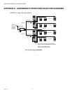
Honeywell Meter Connections
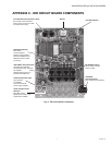
1. Each Honeywell meter has two modular jacks located at
the top of the main circuit board. The jack on the left
(RJ-45, 8-pin), labeled “IDR”, is used to connect the
meter to the IDR. NEVER USE THE 6-PIN JACK
LOCATED ON THE RIGHT SIDE OF THE METER CIR-
CUIT BOARD TO CONNECT ANY IDR.
2. * Be sure that one Honeywell meter is located within
100 feet of the IDR. This meter will be used to supply
the low-voltage power necessary to operate the IDR.
Connect this meter to jack #1 on the IDR using an 8-
conductor flat modular cable. (See Chapter 5.0 if the
IDR has the optional AC adapter.)
3. *All remaining Honeywell meters must be connected to
the meter jacks #2-8 using 6-conductor flat modular
cable.
4. SUBIDR-16 - If the IDR is an SUBIDR-16, connect the
additional meters to Jacks # 9-16 on the option card
using 6-conductor flat modular cable.
5. SUBIDR-8s orSUBIDR-16s supplied with plug-in screw
type connectors can be up to 500 feet from all meters,
and utilize a pair of wires for connecting to the meter
pulse output.
* See Appendix C for items 2 & 3 above.
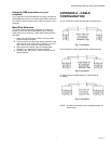
** For more information on cable assembly, see Appendix A.
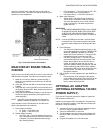
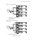
Pulse Output Meters (IDR-ST models only):
1. Each meter is interfaced with the IDR through the plug-
in screw type connectors. Any of the connectors may be
used with #22-14 AWG conductors.
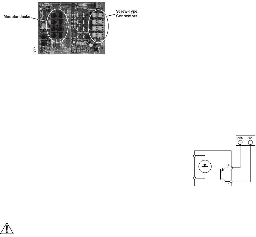
2. When used with solid-state switches, correct polarity
must be observed in order for that contact to be recog-
nized. COM (or “C”) on the IDR is 12 VDC that must be
connected to the + side of the pulse switch. The return
side of the switch is connected to SIG (or “S”) on the
IDR.
Fig. 4. Observe polarity when using solid-state switches
with pulse output meters.
3. The meter can be up to 500 feet away from the IDR.
Third-Party Meter Connections
In order to connect “third-party” meters such as gas, water or
utility-type meters, the IDR must be ordered with the screw
terminal connectors (designated with the suffix B or C at the
end of the model number) instead of the modular jacks.
The IDR for third-party metering is always powered by the
optional AC adapter power supply and requires an available
120 VAC receptacle to obtain the power. The receptacle must
not be switched off at any time. See Section 5.0, Optional AC
Adapter.
The input pulses supplied to the IDR must be non-powered,
and they can be either physical (mechanical) contacts or
electronic switches. When electronic switches are used, the
“COM” terminal on the IDR is the “+” output and the “SIG” is
the return from the switch.
The IDR with modular jacks automatically detects when an
Honeywell meter is connected to it so that it can be
recognized by the software when the meters are added or