


SUB SERIES INTERVAL DATA RECORDERS
62-0342—01 8
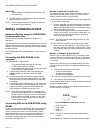
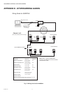
APPENDIX D - SYSTEM WIRING GUIDES
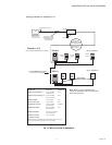
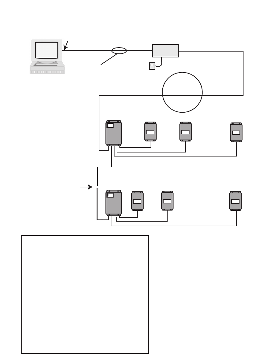
Fig. 12. Wiring overview for SUBIDR-8.
Note: Meter 1 must be installed within
100 feet of IDR. Meters 2-8 must be installed
within 500 feet of IDR.
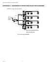
(Up to 8 Meters)
(One of three channels shown for clarity.)
(Up to 8 Meters)
~
~
Channel 1 of 3
4-Conductor
Flat Modular Cable
Up to 4000 Feet Total
Daisy-Chain or
Star Connection
Up to 52 SUBIDR-8s per channel
AC Adapter
SUB-RS232K
6' cable provided by
Honeywell (15 ft max.)
8-conductor cable
& modular plug
DB-9 (DTE) Connector
PC
RJ-45
RJ-11
8-Cond.
RJ-45
RJ-11
6-Cond.
RJ-45
6-Cond.
RJ-45
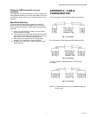
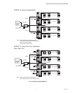
Wiring Guide for SUBIDR-8
IDR A
IDR Z
CONNECTION CABLE TYPE CONNECTOR
SUBIDR to Honeywell Meter #1 8-cond. 22-26 AWG RJ-45
flat modular cable
SUBIDR to Honeywell Meters #2-8 6-cond. 22-26 AWG RJ-45
(Pins 1 & 8 not used)
SUBIDR to SUBIDR 4-cond. 26 AWG RJ-11
SUBIDR to SUB-RS232K 4-cond. 26 AWG RJ-11
SUB-RS232K to Computer * 8-cond. 22-26 AWG RJ-45/DTE
flat modular cable
SUB-RS232K to Modem * 8-cond. 22-26 AWG RJ-45
flat modular cable
SUBIDR to SUB-USBK * Allows connection directly
to the computer USB
SUBIDR to Pulse Meter 2-cond. 14-22 AWG
* Supplied by Honeywell
Note: When constructing field-installed cables, modular cables must be made
so that the individual wires go through on the same pin number.