


SUB SERIES INTERVAL DATA RECORDERS
62-0342—01 4
IMPORTANT:
The AC adapter is designed to be used with a 120
VAC outlet only.
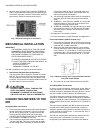
5. The IDR should now be energized. Perform the visual
checks outlined in section 4.
NOTE: The AC adapter provides an isolated 18 VAC/300
mA power source for the IDR.
SERIAL COMMUNICATIONS
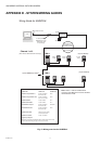
Hardwired System using the SUB-RS232K
Communication Key.
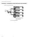
(See the hardwired system configuration diagrams in
Appendix F.)
The SUB-RS232K communications key allows you to connect
IDRs to a personal computer that has E-Mon Energy software
installed. The computer communicates with the IDRs through
the SUB-RS232K.
The SUB-RS232K must be located within 15 feet of the host
computer.
Connecting the SUB-RS232K to the
computer
The SUB-RS232K is supplied with:
• (1) 8-conductor cable fitted with RJ-45 plugs
• (1) DB-9 serial COM port adapter
• (1) AC adapter that converts 120 VAC into the 7 VAC
used to power the SUB-RS232K.
1. Connect the 8-conductor cable to the left-side jack
(labeled “RS232”) on the rear panel of the SUB-
RS232K.
2. Connect the appropriate COM port adapter (DB-9) to
the serial port on the back of the computer. Plug the 8-
conductor cable from the SUB-RS232K into the COM
port adapter.
3. Connect the 7 VAC AC adapter into the rear panel input
on the SUB-RS232K. Plug the adapter into a 120 VAC
outlet. On the front panel of the SUB-RS232K, two
LEDs will light up (POWER ON and AC ON.)
NOTE: When E-Mon Energy software is accessed on the
computer, a third LED will turn on. The SUB-RS232K
READY indicator will light up as soon as the E-Mon
Energy software is booted up and the correct COM
port is set up via the settings provided in the soft-
ware’s Locations menu.
Connecting IDRs to the SUB-RS232K using
RS-485
On the rear panel of the SUB-RS232K, there are three jacks
labeled as channels A, B and C. These are RS-485 serial
communications ports used to connect the IDRs. Each of
these three channels can be connected to as many as 52
individual IDRs over a total cable distance of 4000 feet.
Channels are independent and must not be connected to
each other. (See Appendix F.)
METHOD 1: MODULAR PLUG METHOD
This method requires using 4 stranded conductors inside a
cable that is fitted with an RJ-11 type plug for 4-conductor
modular systems at each end of the cable.
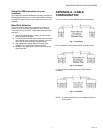
* Do not use any pre-made telephone cables. See Appendix A
for correct cable configuration.
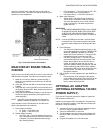
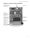
1. Plug the 4-wire RJ-11 cable/plug assembly into Channel
A on the SUB-RS232K. Connect the other end of this
cable to the IDR at either of the two RS-485 ports at the
top left of the IDR circuit board.
2. The unused RS-485 port is used to connect another
cable to the next IDR. This is called a “daisy-chain” con-
nection. This can be done repeatedly to connect as
many as 52 individual IDRs.
NOTE: The total combined cable length must be no more
than 4,000 feet.
3. Each IDR has two LEDs (yellow and green) located
directly below the RS-485 jacks. If the system is prop-
erly wired, these two LEDs will normally be OFF. These
LEDs will flash when the computer and IDR are commu-
nicating.
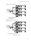
METHOD 2: TERMINAL BLOCK METHOD
IDRs may also be daisy-chained using a 3-conductor cable.
Instead of using the two modular jacks for the RS-485 daisy
chain, you can use J20 at the bottom right corner of the IDR
circuit board.
Remove this 3-terminal plug to facilitate attaching the wires
using the screw terminals that are captivated within the plug
housing.
1. 1. Daisy-chain the IDRs by connecting:
• All HI terminals together
• All LO terminals together
• All GND terminals together
** This requires putting two wires into each of the 3 terminals.
2. Connecting to the SUB-RS232K.
You will need to attach an RJ-11 modular plug to the cable that
serves the RS-485 system.
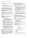
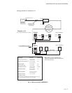
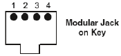
On each channel on the back of the SUB-RS232K, the pin out
for each channel is as follows:
Fig. 6. SUB-RS232K modular jack pin out.
• PIN1 - Not used
• PIN2 - GND
•PIN3 - HI
• PIN4 - LO
NOTE: It is okay to use the J20 with the modular jacks if
needed.
This completes the installation of the IDR hardwired system.