14
Snapshot Mode
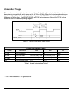
In the Snapshot mode of operation, image acquisition begins on the rising edge of the Trigger signal.
Image integration continues until the trigger line is brought low at which time the Image Data is output on the
Camera bus. In this mode, the area illumination is coincident with the integration time and is activated on the
rising edge of the Trigger signal. The illumination will remain on until the FirstFlash circuitry determines that
sufficient light has reached the sensor. At that point, the FirstFlash circuitry will then automatically disable
illumination. The user can override the FirstFlash circuitry by activating the Illum_On signal along with the
Trigger signal. For additional information, refer to Snapshot Illumination Waveforms on page 15.
The minimum Trigger pulse time required to initiate image acquisition in Snapshot mode can be calculated
using the following formula:
Ttrig_min = 84 + (<image-height> + 19) * 9 / PCLK
Where PCLK is the pixel clock output of the image sensor
and can be programmed to 48 MHz, 24 MHz, or 12 MHz.
For example, in systems that cannot support 48 MHz pixel clock rates (such as Xscale PXA270 processor
based platforms) the pixel clock can be reduced to 24 MHz or 12 MHz. Thus, for the default image height of
960 rows at 24 MHz pixel clock, the Trigger pulse time should be at least 451 µs.
As mentioned above, the trigger pulse controls both the image integration time and the maximum duration of
the illumination. The maximum time is application specific. Increasing the time will typically result in brighter
images but longer exposure time will make the unit susceptible to motion blur.
Software used by the engine device driver and CamLib APIs included in the Software Development Kit provide
the ability for precise control of the timings of the Trigger signal, the image sensor, and the image dataflow
from the camera to the host system.
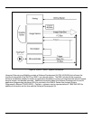
The actual time of the illumination flash in Snapshot mode can vary between the minimum illumination time
and the maximum illumination time. The maximum illumination time is determined by the duration of the
Trigger signal. The minimum illumination time is determined by the duration of the Illum_On signal. The actual
time of the illumination flash is determined by the internal Microcontroller based on the measurement of the
light intensity performed by the FirstFlash circuitry.
When the light intensity, as measured by the FirstFlash circuitry, exceeds a pre-set factory threshold, the
Microcontroller immediately turns illumination off if the time elapsed from the start of illumination is greater than
the minimum illumination time (i.e. if the Illum_On signal is de-asserted); otherwise, it waits until the minimum
illumination time elapses and then turns the illumination off.
Precise control of the timings of the Illum_On signal is done in software by the engine device driver and
CamLib APIs included in the Software Development Kit.


