16
Video Mode
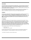
The Video Mode allows for streaming video from the CMOS imager. The main advantage in the mode is that
the user has fine control over the exposure time. Fine control over the exposure time makes this mode well
suitable for high ambient light applications. The Video Mode is initiated through commands via the I
2
C bus.
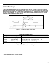
During this mode of operation, the Trigger signal must be held low. If lighting is required, the Illumination LEDs
can be controlled via the Illum_On control signal.
Control of all signals and image dataflow in Video Mode is done in software by the engine device driver and
CamLib APIs included in the Software Development Kit. See SDK documentation for more details.
When not in Video Mode, the image sensor is always ready for Snapshot image acquisition.
Targeting
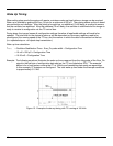
The engine uses a targeting LED to indicate the center of the imaging field. This LED can be activated at any
time by asserting the Aimer signal. The targeting LED is independent of the mode of operation and
illumination. However, it is strongly recommended that the targeting LED not be activated during image
acquisition as the light from the targeting LED will be visible in the image and may result in “hot
spots”. Control of the aiming mechanism is done in software by the IS4910 device driver and CamLib APIs
included in the SDK.
I
2
C Interface
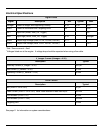
The IS4910 series engines use an I
2
C compliant interface to communicate with the host system. The bus
allows the host to communicate directly with the image sensor and illumination microcontroller. Both of these
devices function as auxiliary* devices on the bus. The illumination Microcontroller is capable of running at
speeds up to 100 kHz whereas the image sensor can support frequencies up to 400 kHz. The standard
configuration of the IS4900 series of imaging engines does not incorporate pull up resistors on the SDA and
SCL lines in order to allow flexibility for the end user when choosing the resistor values. These resistors must
be provided by the host system and sized to meet the I
2
C timing requirements. Timing provided by the I
2
C bus
specification must be observed in order to guarantee proper operation of the engine.
The two I
2
C devices used in the IS4910 Engine use the following addresses:
• CMOS Image: 0x10
• Illumination Micro: 0x61 and 0x70
For details regarding programming of the image sensor, please refer to documentation provided with the
Software Development Kit. For details regarding the I
2
C protocol, see the Phillips I
2
C specification.
* In the Phillips I
2
C specification, auxiliary is defined as slave.


