Installing the NetAXS-123 Panels
Installation
NetAXS-123 Access Control Unit Installation Guide, Document 800-05779, Revision A 29
3.4 Wiring the Readers
Each reader port supports one or two readers (entry and exit readers) with Wiegand output format. The
maximum power draw is 500 mA for readers and AUX Power combined.
To fully utilize each reader port, a shielded 7-conductor cable (18-22 AWG) is required. If you don’t
need the HOLD LINE feature, you can use the standard 6-conductor cable (HAS part number
NC186-BL).
Note: If you are using additional HOLD lines for readers, you will need an 8-conductor cable.
The cable shield should be grounded at the panel only. Grounding at both ends can cause ground loops
which can be disruptive. The maximum recommended length of wiring is 500 feet per reader.
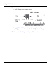
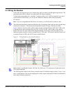
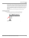
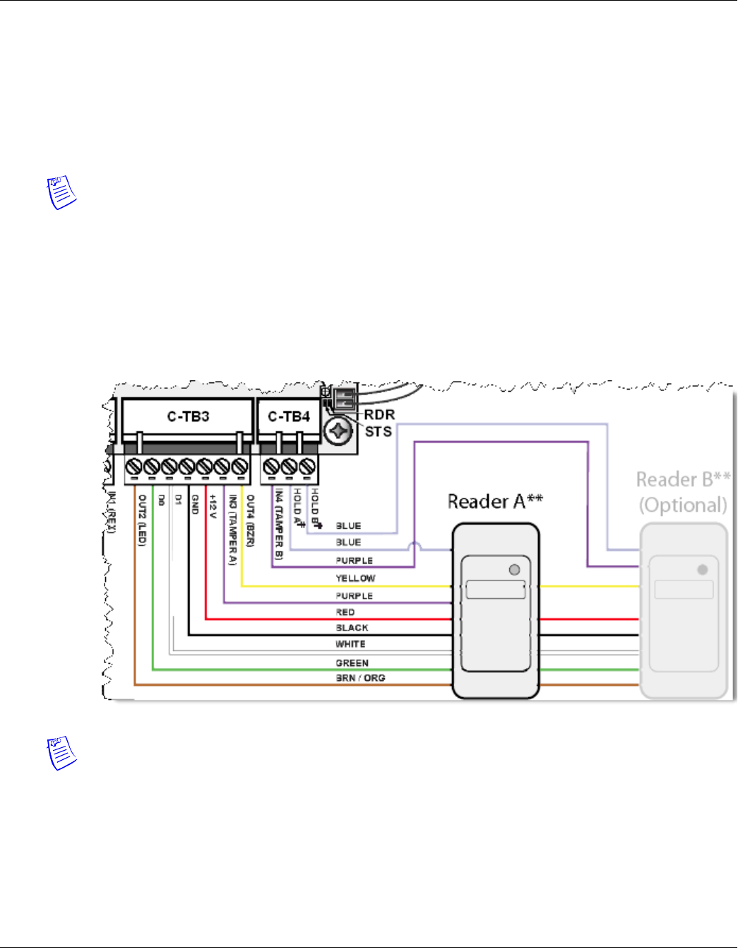
Figure 5 shows a one-door panel, with the readers wired to terminal blocks C-TB3 and C-TB4 on the
Controller Board, and to terminal blocks IO-TB3, IO-TB4, IO-TB7, and IO-TB8 on the Add-On
Board. The wires are color-coded to their labeled terminals. If this were a two-door panel, the two
additional readers would be wired to terminal blocks C-TB1 and C-TB2 on the Controller Board, and
to terminal blocks IO-TB1 and IO-TB2 on the Add-On Board.
Figure 5: Wiring Readers to the Controller Board
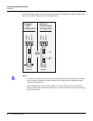
Note: Reader A and Reader B share LED, DO, D1, GND, and +12V connections. Each reader has its
own Tamper and Hold.
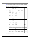
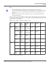
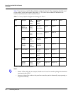
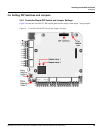
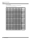
The following three tables list the factory controller board I/O default settings for door-1, door-2, and
door-3 configurations. These are the mappings for readers, inputs, and outputs. Reader A and Reader B
share many common connections.


