


Pub. 42004-693L2C
Model 69320-101 Voice Network Adapter Page: 3 of 15
\\s_eng\gtcproddocs\standard ioms - current release\42004 instr. manuals\42004-693l2c.doc
04/06
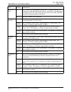
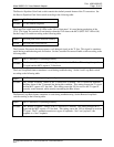
LED Status Description
LOS/RCL
(red)
On
The VNA is not receiving a T1 signal (Loss of Signal or Receive Carrier
Loss), and does not detect an open on its T1 transmit line.
Flashing
90% On
The VNA both is not receiving a T1 signal and detects an open on its T1
transmit line. The frequency of flashing is approximately one Hertz.
Flashing
50% On
The VNA detects an open on its T1 transmit line, and is receiving a T1 signal.
The frequency of flashing is approximately one Hertz.
Flashing
10% On
The T1 transceiver on the VNA is not initialized. The frequency of flashing is
approximately one Hertz.
Off
All of the above four conditions are not occurring.
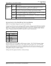
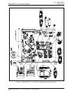
Connections to the Field Wiring Terminal Blocks
69320-101 Voice Network Adapter Connections to the Field Wiring
Connections to the field are made via the upper DB25 connector on the rear of the 10457 Series Card Rack
assembly. This connector can be utilized by a direct connection of a DB25 cable to the field equipment, a
DB25 cable to a DIN rail-mounted terminal block adapter, or with the use of a DB25-to-RJ45 connector
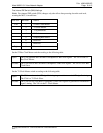
adapter. The pinout definition for the DB25 connection is shown is the table below.
Upper DB25 Connector
Pin Signal
1 Tx (ring)
2 Tx (tip)
5 Rx (ring)
6 Rx (tip)
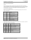
Included with the VNA are two DB25-to-RJ45 connector adapters. The 21246-014 Connector Adapter
brings the transmit pair to the RJ45 pins 1 and 2 and the receive pair to pins 4 and 5. The 21246-008
Connector Adapter brings the transmit pair to the RJ45 pins 4 and 5 and the receive pair to pins 1 and 2.
These adapters permit the use of non-crossover Ethernet cables for the connections to field equipment
utilizing these same pins on an RJ45 connector.
Cabling to the field equipment should be a twisted pair design.