


Page 3 of 8 Version 1.0 11/08/01
Memory Interface:
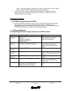
v Extended SDRAM Addressing
Ø The signal MADDR13 has been added to support the following additional SDRAM
organizations:
§ 13-12-2, 14-9-2, 14-10-2, 14-11-2, 14-12-2
§ Register SDRAM0_MCER [26:29] is used to select the SDRAM organization; refer to
the CPC710-133 User’s Manual for more information.
v Extended Memory Size
Ø The Memory controller has been modified to support up to six banks of dual DIMM
interleaved 72-bit memory, for a total memory addressing range of 3.5GB. The memory
controller now allows configuration of bank sizes up to 4GB per bank
The choice of 4MB to 1GB (same as the CPC710-100+) or 4MB to 4GB is made with
SDRAM0_MCCR [8].
§ If SDRAM0_MCCR [8] = 1 bank size range is from 4MB to 1GB
§ If SDRAM0_MCCR [8] = 0 bank size range is from 4MB to 4GB
§ Refer to the CPC710-133 User’s Manual for more information.
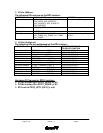
v Supported Memory Types
Ø Supports JEDEC standard PC100 and PC133 SDRAMs, both single bank and dual bank.
Ø EDO memory is no longer supported on the CPC710 with the DD3.x revision.
Ø All types of registered DIMMs are now supported on the CPC710 with the DD3 version.
New programming bits are defined in register SDRAM0_MCCR0 to support registered
DIMMS.
§ Setting SDRAM0_MCCR [16] = 1 adds one additional clock cycle to the internal
sequencer signals for read operations of registered DIMMs.
§ Setting SDRAM0_MCCR [19] =1 shifts the following signals by one clock cycle:
MUX_SEL, MUX_CLKEN1B_, MUX_CLKEN2B_
§ Setting SDRAM0_MCCR [21] = 1 allows the data to be written to the memory to be
held valid for an additional clock cycle.
§ Setting SDRAM0_MCCR [22] = 1 shifts the following signals by one clock cycle:
MUX_CLKENA2_, MUX_OEB_, SDRAS0_, SDRAS1_, SDCAS0_, SDCAS1_, WE0_,
WE1_, MADDR0_ODD, MADDR0_EVEN, MADDR1-13, BS0 and BS1
v Maximum Number of Memory Banks Decreased from 8 to 6
Ø CPC710 DD3.x revision does not support the use of registers MCER6 and
MCER7.These registers were present in the CPC710-100+ DD2 version.
Ø Internal memory controller logic no longer generates SDCS12_ through SDCS15_. These
signals were present in the CPC710-100+ DD2 version. The multiplexing capabilities
defined in register SDRAM0_MCCR [11:15] have been modified from the usage in
CPC710 DD2 revision. This multiplexing allows for support of SDRAM speeds up to 133
MHz. The higher speed is attained by limiting the loading (number of SDRAM packages)
on each SDCS signal.
§ New encoding:
• If SDRAM0_MCCR [11] = 1 signals SDCS_[0:3] use I/O pins SDCS_[4:7]
• If SDRAM0_MCCR [12] = 1 signals SDCS_[0:3] use I/O pins SDCS_[8:11]
• SDRAM0_MCCR [13] is no longer used
• If SDRAM0_MCCR [14] = 1 signals SDQM use I/O pins SDRAS1_, SDCAS1_
and WE1_
• If SDRAM0_MCCR [15] = 1 signals SDQM uses I/O pins PCG_ARB