


NetBAY Power Distribution Units 143
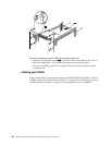
Note: The mounting holes on the upper and lower side braces in a rack side
compartment must be between 48.6 cm (19.1 in.) and 56.9 cm (22.4 in.) apart. If
your rack cabinet has movable side braces, refer to your rack documentation
for information about relocating your side braces if they are not already spaced
for this installation.
1. Refer to the documentation that comes with your rack cabinet for additional
information.
Note: Removing the rack doors and side panels might make your Rack PDU
installation easier.
2. Verify that the circuit breaker switch is in the Off position before installing your
Rack PDU.
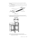
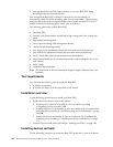
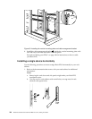
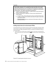
3. Install the Rack PDU
3 to the vertical mounting plate 2 with four M3x5
screws
1 that come with this option. Make sure that the countersink holes in
the vertical mounting plate are facing away from the device.
Note: Align the Rack PDU to one end or the other of the vertical mounting plate
to leave room for a second device.
Figure 58. Installing the Rack PDU on the vertical mounting plate
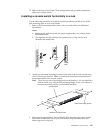
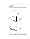
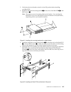
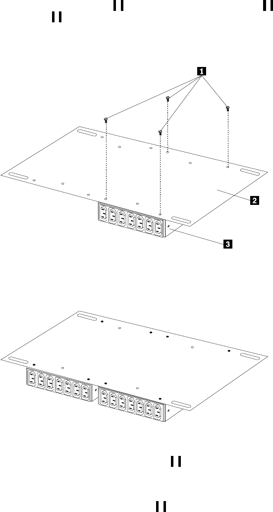
4. If you have a second M/PDU device to install, install it on the vertical mounting
plate with four M3x5 screws that come with the second device.
Figure 59. Installing a second Rack PDU
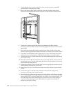
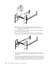
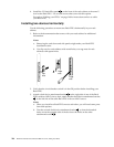
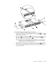
5. Install the vertical mounting plate
2 in the side of your rack cabinet with four
M6 screws and nuts that come with this option. Make sure that the seven-
connector side of the Rack PDU is facing the rear of your rack cabinet, and leave
room between the vertical mounting plate and the rear EIA mounting flanges for
the cable-management bracket
1 .