


Chapter 2. System board features
Delayed transaction
PCI parity checking and generation support
IDE bus master interface
The system board incorporates a PCI-to-IDE interface that complies with the
AT Attachment Interface with
Extensions
.
The
bus master
for the IDE interface is integrated into the I/O hub of the Intel 810 chipset. The chip set is
PCI 2.1 compliant. It connects directly to the PCI bus and is designed to allow concurrent operations on
the PCI bus and IDE bus. The chip set is capable of supporting PIO mode 0–4 devices and IDE DMA
mode 0–3 devices, ATA 66 transfers up to 66 Mbytes/sec.
The IDE devices receive their power through a four-position power cable containing +5, +12, and ground
voltage. When adding devices to the IDE interface, one device is designated as the master device and
another is designated as the slave or subordinate device. These designations are determined by switches
or jumpers on each device. There are two IDE ports, one designated 'Primary' and the other 'Secondary,'
allowing for up to four devices to be attached. The total number of physical IDE devices is dependent on
the mechanical package to a maximum of four.
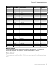
For the IDE interface, no resource assignments are given in the system memory or the direct memory
access (DMA) channels. For information on the resource assignments, see “Input/output address map” on
page 36 and Figure 36 on page 40 (for IRQ assignments).
USB interface
Universal serial bus (USB) technology is a standard feature of the computer. The system board provides
the USB interface with two connectors integrated into the ICH (I/O controller hub) in the chip set. A
USB-enabled device can attach to each connector, and if that device is a hub, multiple peripherals can
attach to the hub and be used by the system. The USB connectors use Plug and Play technology for
installed devices. The speed of the USB is up to 12 Mbps with a maximum of 127 peripherals. The USB
is compliant with Universal Host Controller Interface Guide 1.0.
Features provided by USB technology include:
Support for hot-pluggable devices
Support for concurrent operation of multiple devices
Suitable for different device bandwidths
Support for up to five meters length from host to hub or from hub to hub
Guaranteed bandwidth and low latencies appropriate for specific devices
Wide range of packet sizes
Limited power to hubs
For information on the connector pin assignments for the USB interface, see “USB port connectors” on
page 33.
Low pin count (LPC) bus
On the system board, the Intel ICH1 bridge provides the interface between the peripheral component
interface (PCI) and LPC buses. The chip set is used to convert PCI bus cycles to ISA bus cycles; the
chip set also includes all the subsystems of the ISA bus, including two cascaded interrupt controllers, two
DMA controllers with four 8-bit and three 16-bit channels, three counters equivalent to a programmable
interval timer, and power management. The PCI bus operates at 33 MHz.
Chapter 2. System board features 5