


Chapter 2. System board features
Physical layout
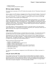
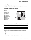
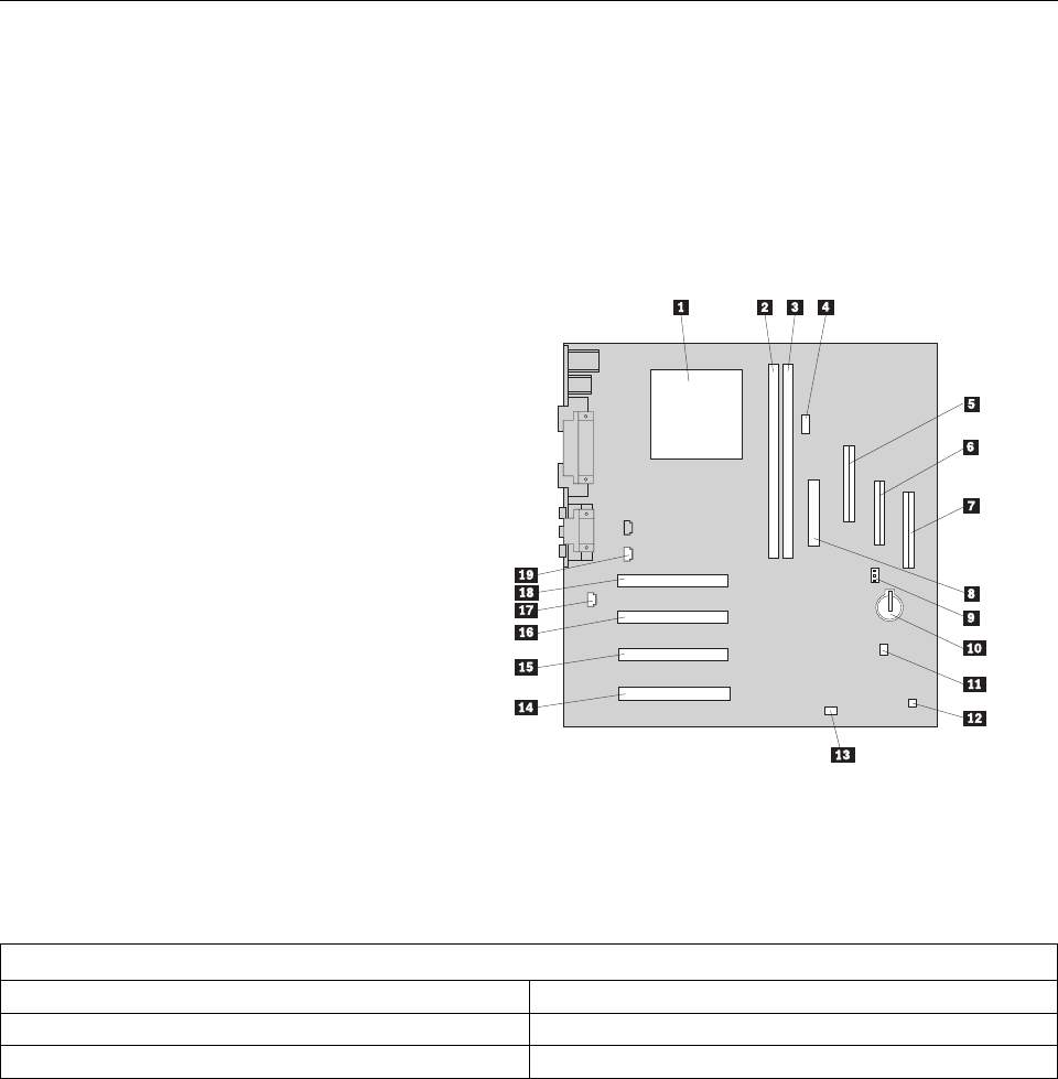
The system board might look slightly different from the one shown.
Note: A diagram of the system board, including switch and jumper settings, is attached to the underside
of the computer cover.
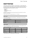
System board, types 6268, 6278, and 6288
Jumper
Jumpers on the system board are used for custom configurations. For the location of the CMOS recovery
jumper, refer to the “System board, types 6268, 6278, and 6288,” above.
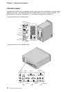
Cable connectors
Connections for attaching devices are provided on the back of the computer. The connectors are:
USB (2)
Mouse
Keyboard
Serial
Parallel
Monitor
Some models only: Ethernet adapter with an RJ-45 connector
Integrated Analog Devices, Inc. audio controller with line in, line out, and microphone connectors
1Microprocessor
2DIMM 0
3DIMM 1
4Alert on LAN connector
5Secondary EIDE connector
6Diskette connector
7Primary EIDE connector
8Power connector
9Fan connector
1Battery
11Wake on LAN connector
12PC/PCI legacy audio adapter
13Clear CMOS/recovery jumper
14PCI adapter slot 4
15PCI adapter slot 3
16PCI adapter slot 2
17Chassis speaker connector
18PCI adapter slot 1
19CD-ROM connector
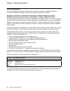
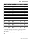
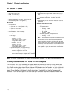
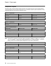
Figure 7. BIOS configuration jumper (J7A1)
Pins Description
1 and 2 Normal (Factory default)
2 and 3 Clear CMOS/Password
Chapter 2. System board features 13