


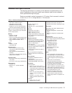
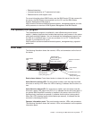

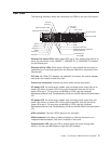

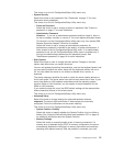
Rear view
The following illustration shows the connectors and LEDs on the rear of the server.
TX/RX TX/RXLINK LINK
Ethernet 2
Ethernet 1
Mouse
Universal Serial
Bus (USB)
Serial
Video
Keyboard
Remote Supervisor Adapter II
EthernetSlimLine
ASM
SCSI
System-locator LED
Ethernet link status LEDs
Ethernet activity LEDs
Power cords
AC power LED
DC power LED
PCI slot 3
PCI slot 2
PCI slot 1
PCI slot 4
Ethernet link status LEDs: When these LEDs are lit, they indicate that there is an
active link connection on the 10BASE-T, 100BASE-TX, or 1000BASE-TX interface
for the Ethernet port.
Ethernet activity LEDs: When these LEDs are lit, they indicate that the server is
transmitting to or receiving signals from the Ethernet LAN that is connected to the
Ethernet port.
PCI slots 1-4: When PCI adapters are installed in the server, the external adapter
connectors are located in these four slots.
Power-cord connectors: Connect the power cords to these connectors.
AC power LED: On some server models, each hot-swap power supply has an ac
power LED and a dc power LED. During typical operation, both the ac and dc
power LEDs are lit. For any other combination of LEDs, see the Hardware
Maintenance Manual and Troubleshooting Guide on the IBM xSeries Documentation
CD.
DC power LED: On some server models, each hot-swap power supply has a dc
power LED and an ac power LED. During typical operation, both the ac and dc
power LEDs are lit. For any other combination of LEDs, see the Hardware
Maintenance Manual and Troubleshooting Guide on the IBM xSeries Documentation
CD.
SCSI connector: Connect a SCSI device to this connector.
ASM connectors: Use either of these connectors to connect the server to an
Integrated xSeries Adapter (IXA) that is installed in the server.
System-locator LED: Use this LED to visually locate the server among other
servers. You can use IBM Director to light this LED remotely.
Chapter 1. Introducing the IBM xSeries 346 Type 8840 9