


Chapter 2 Installations
26 CI5VGM User’s Manual
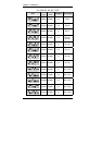
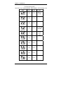
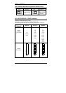
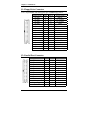
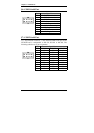
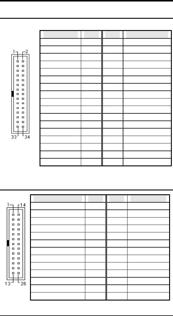
J1: Floppy Drive Connector
J1 is a 34-pin header and will support up to 2.88MB floppy drives.
Signal Name Pin # Pin # Signal Name
Ground 1 2 RM/LC
Ground 3 4 No connect
Ground 5 6 No connect
Ground 7 8 Index
Ground 9 10 Motor enable 0
Ground 11 12 Drive select 1
Ground 13 14 Drive select 0
Ground 15 16 Motor enable 1
Ground 17 18 Direction
Ground 19 20 Step
Ground 21 22 Write data
Ground 23 24 Write gate
Ground 25 26 Track 00
Ground 27 28 Write protect
Ground 29 30 Read data
Ground 31 32 Side 1 select
J1
Ground 33 34 Diskette change
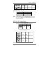
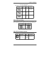
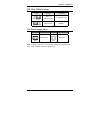
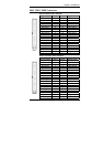
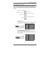
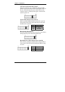
J2: Parallel Port Connector
Signal Name Pin # Pin # Signal Name
Line printer strobe 1 14 AutoFeed
PD0, parallel data 0 2 15 Error
PD1, parallel data 1 3 16 Initialize
PD2, parallel data 2 4 17 Select
PD3, parallel data 3 5 18 Ground
PD4, parallel data 4 6 19 Ground
PD5, parallel data 5 7 20 Ground
PD6, parallel data 6 8 21 Ground
PD7, parallel data 7 9 22 Ground
ACK, acknowledge 10 23 Ground
Busy 11 24 Ground
Paper empty 12 25 Ground
J2
Select 13 N/A N/A