


Chapter 2 Installations
30 CI5VGM User’s Manual
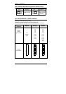
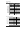
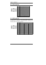
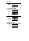
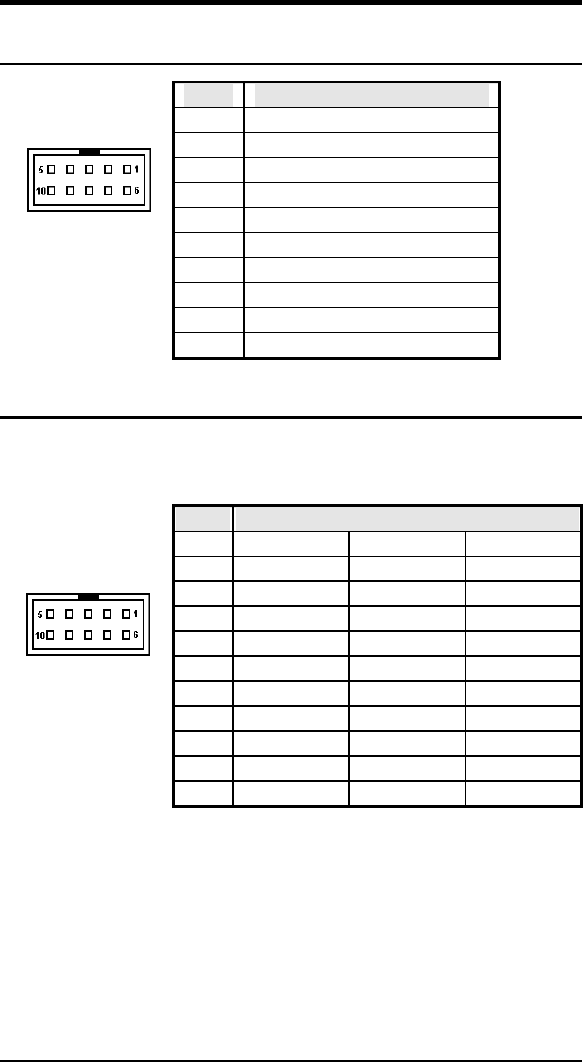
J6: COM1 Serial Port
Pin # Signal Name
1 DCD, Data carrier detect
2 RXD, Receive data
3 TXD, Transmit data
4 DTR, Data terminal ready
5 GND, ground
6 DSR, Data set ready
7 RTS, Request to send
8 CTS, Clear to send
J6
9 RI, Ring indicator
10 NC
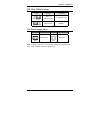
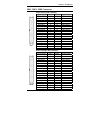
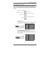
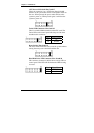
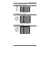
J7: COM2 Serial Port
J7, a 10-pin header connector , is the onboard COM2 serial port of the
CI5VGM and is configurable as RS-232, RS-422 or RS-485. The
following table shows its pin assignments.
Pin # Signal Name
RS-232 R2-422 RS-485
1 DCD TX- DATA-
2 RX TX+ DATA+
3 TX RX+ NC
4 DTR RX NC
5 GND GND GND
6 DSR RTS- NC
7 RTS RTS+ NC
8 CTS CTS+ NC
9 RI CTS- NC
.
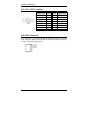
J7
10 NC NC NC