


Chapter 2 Installations
32 CI5VGM User’s Manual
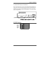
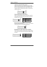
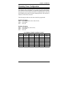
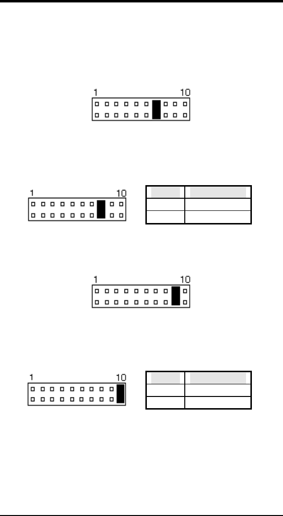
ATX Power ON Switch: Pins 7 and 17
This 2-pin connector is an “ATX Power Supply On/Off
Switch” on the system that connects to the power switch on
the case. When pressed, the power switch will force the
system to power on. When pressed again, it will force the
system to power off.
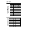
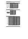
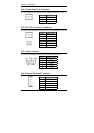
Turbo LED Connector: Pins 8 and 18
There is no turbo/deturbo function on the CPU card. The
Turbo LED on the control panel will always be On when
attached to this connector.
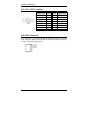
Pin # Signal Name
8 5V
18 Ground
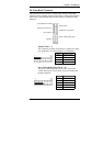
Reset Switch: Pins 9 and 19
The reset switch allows the user to reset the system without
turning the main power switch Off and then On.
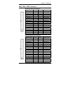
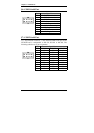
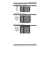
Hard Disk Drive LED Connector: Pins 10 and 20
This connector connects to the hard drive activity LED on
control panel. This LED will flash when the HDD is being
accessed.
Pin # Signal Name
10 HDD
20 5V