


Chapter 3
Functional Details
82C55 emulation
The CIO-DIO48H emulates the 82C55 chip. The 82C55 emulation initializes all ports as inputs on power-up
and reset. A TTL input is a high impedance input. If you connect another TTL input device to the output, it
could be turned on or off every time the board is reset.
To establish a consistent TTL level at power-up, use resistors tied to either +5V (pull-up) or ground (pull-
down). There are open locations for pull-up and pull-down resistor packs on the board.
Whenever an 82C55 emulation is powered on or reset, all pins are set to high-impedance input. Based on
standard TTL functionality, these inputs will typically float high, and may have enough drive current to turn on
external devices.
Consequently, if you have output devices such as solid state relays, they may be switched on whenever the
computer is powered on or reset. To prevent unwanted switching, and to drive all outputs to a known state after
power on or reset, pull all pins either high or low through a 2.2 K resistor.
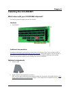
Signal level control
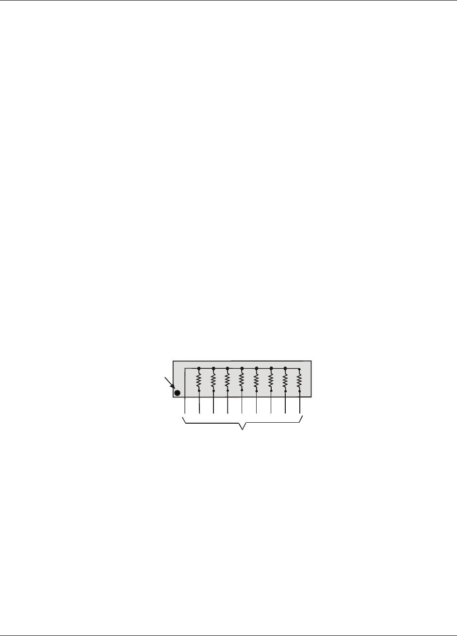
To safeguard against unwanted signal levels, the devices being controlled by the CIO-DIO48H board should be
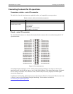
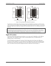
tied low or high as required by a 2.2K Ω resistor. In a 2.2K eight-resistor SIP pack, one side of all of the
resistors is connected to a single common point and brought out to a pin. The common line, usually marked
with a dot or line, is at one end of the SIP. The remaining resistor ends are brought out to the other eight pins
(refer to Figure 4).
2.2KOhm SIP
Dot indicates the
common line
(LO or HI)
I/O Lines
Figure 4. Eight-resistor SIP schematic
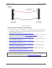
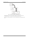
Figure 5 shows a schematic of an SIP installed in both the pull-up and pull-down positions. Each port provides
10 holes in a line. The end labeled
HI connects to +5V. The end marked LO connects to GND. The eight holes
in the middle (n0 –n7) connect to the eight lines of the port (A, B or C).
13