


CIO-DIO48H User's Guide Functional Details
2.2 K SIP installed for pull-up
2.2 K SIP
Dot
+5 VDC
HI
LO
(GND)
n7
User Connector
Digital I/O Lines
n5
n4
n3
n2
n1
n0
n6
COM
Digital
I/O
Port
n = A, B, or C
2.2 K SIP
Dot
+5 VDC
HI
LO
(GND)
n7
User Connector
Digital I/O Lines
n5
n4
n3
n2
n1
n0
n6
COM
2.2 K SIP installed for pull-down
Digital
I/O
Port
n = A, B, or C
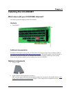
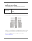
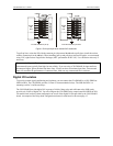
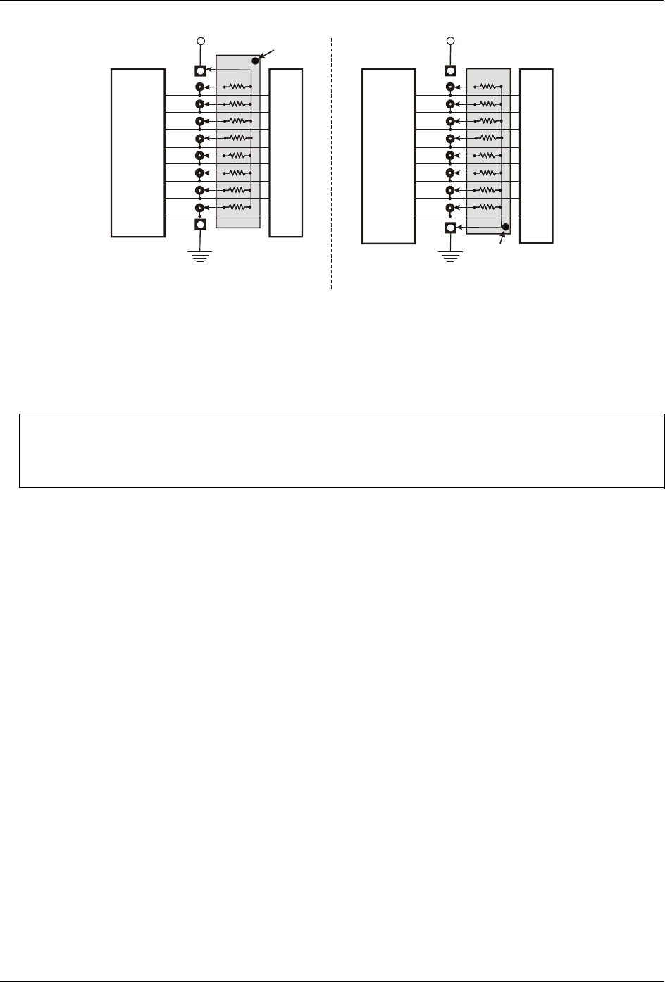
Figure 5. Pull-up and pull-down resistor SIPs schematic
To pull-up lines, orient the SIP with the common pin (dot) toward the HI end; to pull-down, install the resistor
with the common pin in the
LO hole. When installing pull-up and pull-down resistor SIP packs, we recommend
using 2.2K, eight-resistor Single Inline Packages (MCC part number SP-K2.29C). Use a different value only if
necessary.
Unconnected inputs float
Unconnected inputs typically float high, but not reliably. If you are using a CIO-DIO48H for input and have
unconnected inputs, ignore the data from those lines. You do not have to terminate input lines. Unconnected
lines will not affect the performance of connected lines. Mask out any unconnected bits in software.
Digital I/O Isolation
To provide external signal conditioning and isolation, you can connect the CIO-DIO48H to a CIO-ERB24 or
SSR-RACK24. The CIO-ERB24 provides 24 Form C electromechanical relays. The SSR-RACK24 is a
mounting rack for 24 solid-state relays.
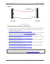
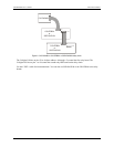
The CIO-DIO48H provides digital I/O in groups of 48 bits. Many relay and solid-state relay (SSR) racks
provide only 24-bits of digital I/O. You can configure the CIO-ERB24 relay output board and SSR-RACK24
I/O module rack in a daisy chain configuration to use all of the digital I/O bits provided by the CIO-DIO48H
board. An example of the daisy chain configuration scheme for each board is shown on page 15.
14