


ETX-DB-ATX
23
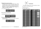
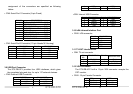
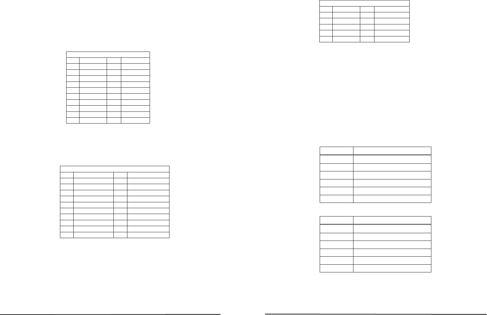
3.18 ATX power connector
•
PW1: ATX power connector pin assignment
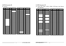
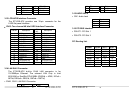
3.19 Front Panel Pin Header
•
CN17: Front Panel Pin Header pin assignment
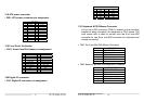
3.20 Digital IO connector
•
CN1: Digital IO connector pin assignment
ATX(PW1)
PIN NAME PIN NAME
1 +3.3V 11 +3.3V
2 +3.3V 12 -12V
3 GND 13 GND
4 +5V 14 PS_ON
5 GND 15 GND
6 +5V 16 GND
7 GND 17 GND
8 PWR OK 18 -5V
9 STB5V 19 +5V
10 +12V 20 +5V
Font Panel Pin Header (CN17)
PIN NAME PIN NAME
1 Power LED+ 2 External Buzzer+
3 Power LED+ 4 GND
5 GND 6 Internal Buzzer-
7 K/B Lock 8 External Buzzer-
9 Power LED- 10 N.C.
11 Power Button1 12 HDD LED-
13 Power Button2 14 HDD LED+
15 N.C. 16 N.C.
17 N.C. 18 Reset button1
19 GND 20 Reset button2
ETX-DB-ATX
24
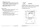
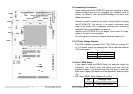
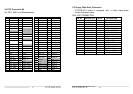
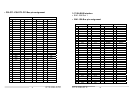
3.21 Keyboard & PS/2 Mouse Connector
A 6-pin mini DIN connector (CN6) is located on the mounting
bracket for easy connection to a keyboard or PS/2 mouse. The
card comes with a cable to convert from the 6-pin mini-DIN
connector to two 6-pin mini-DIN connector for keyboard and
mouse connection
• CN6: Top 6-pin Mini-DIN Mouse Connector
PIN NO. DESCRIPTION
1 MOUSE DATA
2 N.C.
3 GROUND
4 +5V
5 MOUSE CLOCK
6 N.C.
• CN6: Bottom 6-pin Mini-DIN Keyboard Connector
PIN NO. DESCRIPTION
1 KEYBOARD DATA
2 N.C.
3 GROUND
4 +5V
5 KEYBOARD CLOCK
6 N.C.
Digital IO(CN1)
PIN NAME PIN NAME
1 GND 2 +5V
3 OUT3 4 OUT2
5 OUT1 6 OUT0
7 IN3 8 IN2
9 IN1 10 IN0