


ETX-DB-ATX
9
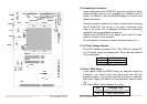
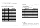
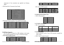
2.5 WatchDog Timeout Active Selector
Reading I/O port 443H enables the WatchDog Timer. It should
be triggered before the time-out period ends, otherwise it will
assume the program operation is abnormal and will issue a
reset signal or an interrupt signal. The Watch-Dog Timer is
disabled by reading port 043/843H.detail information on
WatchDog Timer Refer to Appendix A
• JP7: WatchDog Active Select
JP7 DESCRIPTION
1-2 RESET
2-3 IRQ11
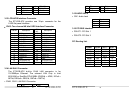
2.6 Internal Buzzer Enable/Disable
• CN17 Pin 6 & Pin 8: Internal Buzzer Enable/Disable
CN17 Pin 6 & Pin 8 DESCRIPTION
On(short) Enable
Off(open) Disable
2.7 Ethernet Controller Setting
The On Board Ethernet Controller can be enable or disable by
selecting the JP10.
JP10 DESCRIPTION
1-2 Enable
2-3 Disable
ETX-DB-ATX
10
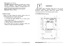
Connection
This chapter describes how to connect peripherals, switches
and indicators to the ETX-DB-ATX board.
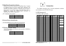
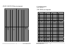
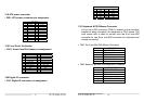
3.1 ETX Connector X1
X1: PCI-Bus, USB, and Audio
PIN SIGNAL PIN SIGNAL PIN SIGNAL PIN SIGNAL
1 GND 2 GND 51 5V 52 5V
3 PCICLK3 4 PCICLK4 53 PAR 54 SERR#
5 GND 6 GND 55 PERR# 56 RESERVED
7 PCICLK1 8 PCICLK2 57 PME# 58 USB2#
9 REQ3# 10 GNT3# 59 LOCK# 60 DEVSEL#
11 GNT2# 12 3.3V 61 TRDY# 62 USB3#
13 REQ2# 14 GNT1# 63 IRDY# 64 STOP#
15 REQ1# 16 3.3V 65 FRAME# 66 USB2
17 GNT0# 18 RESERVED 67 GND 68 GND
19 5V 20 5V 69 AD16 70 CBE2#
21 SERIRQ 22 REQ0# 71 AD17 72 USB3
23 AD0 24 3.3V 73 AD19 74 AD18
25 AD1 26 AD2 75 AD20 76 USB0#
27 AD4 28 AD3 77 AD22 78 AD21
29 AD6 30 AD5 79 AD23 80 USB1#
31 CBE0# 32 AD7 81 AD24 82 CBE3#
33 AD8 34 AD9 83 5V 84 5V
35 GND 36 GND 85 AD25 86 AD26
37 AD10 38 LINE-IN-L 87 AD28 88 USB0
39 AD11 40 MIC 89 AD27 90 AD29
41 AD12 42 LINE-IN-R 91 AD30 92 USB1
43 AD13 44 ASVCC 93 PCIRST# 94 AD31
45 AD14 46 LINE-OUT-L 95 INTC# 96 INTD#
47 AD15 48 ASGND 97 INTA# 98 INTB#
49 CBE1# 50 LINE-OUT-R 99 GND 100 GND
3