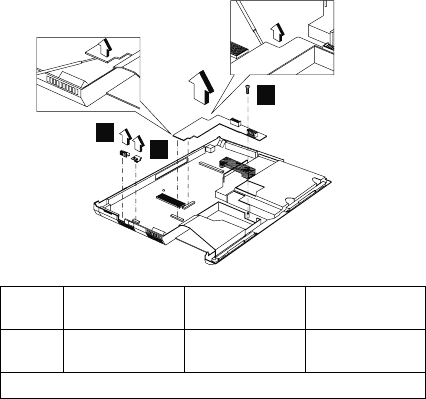
Power Latch, IR Board, and DC-DC &
BATT Board
“Battery” on page 61
“Hard Disk Drive” on page 62
“Combo Bay” on page 63
“Keyboard” on page 70
“LED Board” on page 72
“Upper Heatsink” on page 73
“CPU Board” on page 76
“LCD Panel” on page 77
“Upper Cover” on page 79
“IMM Lower Heatsink” on page 81
“Fan” on page 82
To remove these boards and latch:
1. Remove the power latch.
2. Remove the IR board.
3. Remove the screw securing the DC-DC & BATT
board (using the 1/8" alignment tool) and disconnect
the DC-DC & BATT board from the base cover.
1
2
3
Step
Size (Quan-
tity)
Head &
Color Torque
3 M2.5 x 6L (1) Flat head,
black
2.0 kgf-cm
Note: Make sure you use the correct screw for replacement.
ThinkPad 390X / i 1700 HMM 85


