


9
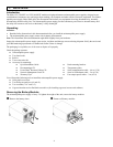
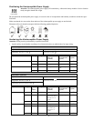
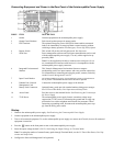
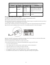
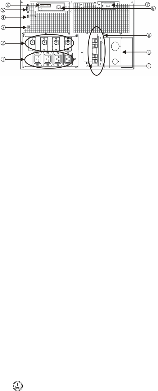
Connecting Equipment and Power to the Rear Panel of the Uninterruptible Power Supply
INDEX ITEM DESCRIPTION
1 Outlets Connect equipment to the uninterruptible power supply.
2 Output Circuit Breakers Each circuit breaker protects its nearest outlet.
3 EPO Terminal The optional Emergency Power Off (EPO) feature enables connected
loads to be immediately de-energized from a remote location, without
switching to battery operation. See Emergency Power Off (EPO) Option.
4 Bypass Switch This switch will put the unit in bypass mode. See Operation.
5 Serial Port
Power management software and serial port communication can be used
with the uninterruptible power supply. Use only cables supplied or ap-
proved by IBM.
Note: Use the supplied serial cable to connect to the serial port. Do not
use a standard serial interface cable because it is incompatible with the
uninterruptible power supply connector.
6 Integrated Environmental
Monitor
This Network Management Card monitor features a tempera-
ture/humidity probe, two input contacts, and a two-position output relay.
For information on connecting and using the probes, contacts, and relay,
see the Network Management Card CD.
7 Input Circuit Breaker
The uninterruptible power supply is protected from extreme overloads when in
the on position.
The breaker must be on for the unit to operate.
8 Ethernet Port/ Network
Management Card
Connect the uninterruptible power supply to the network.
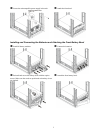
9 Battery Pack Connectors Optional battery packs provide extended runtime during power outages.
See 3U Extend Run Battery Pack Operation and Setup Guide.
10 Access Panel Provides access to the terminal blocks. See Hardwiring the Uninterrupti-
ble Power Supply.
11 TVSS Screw The uninterruptible power supply features a transient voltage surge-
suppression (TVSS) screw for connecting the ground lead on surge sup-
pression devices such as telephone and network line protectors. When
connecting a grounding cable, disconnect the uninterruptible power sup-
ply from the utility power outlet.
Startup
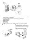
1. Hardwire the uninterruptible power supply. See Hardwiring the Uninterruptible Power Supply.
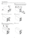
2. Connect equipment to the uninterruptible power supply.
3. Turn on all connected equipment. To use the uninterruptible power supply as a master on/off switch, be sure all connected
equipment is turned on.
4. Press the
button on the front panel to turn on the uninterruptible power supply.
5. Select the ouput voltage (default is 230 V). See Setting the Output Voltage via Terminal Mode.
Note: For setting the number of external battery packs through Terminal Mode, see the 3U Extend Run Battery Pack Op-
eration and Setup Guide.
6. Configure the Network Management Card (optional).