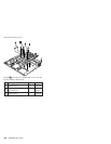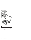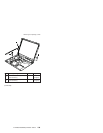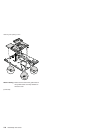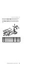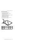
1200 System board, interposer card,
and base cover
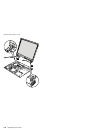
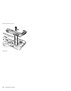
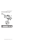
For access, remove these FRUs, in order:
v “1010 Battery pack” on page 68
v “1020 Ultrabay Enhanced device” on page 69
v “1030 Hard disk drive” on page 70
v “1040 DIMM (optional)” on page 72
v “1050 Keyboard” on page 73
v “1060 DIMM (standard)” on page 77
v “1070 Modem daughter card (MDC/MDC-2)” on page 78
v “1080 Bluetooth/Modem daughter card
(BMDC/BMDC-2)” on page 80
v “1090 Keyboard bezel” on page 82
v “1100 Mini PCI adapter” on page 86
v “1110 Fan assembly” on page 90
v “1120 CPU” on page 91
v “1130 Backup battery” on page 92
v “1140 Speaker assembly” on page 93
v “1150 IEEE 1394 cable” on page 95
v “1160 PC Card slots assembly” on page 98
v “1170 Ultrabay Enhanced shield kit” on page 100
v “1180 LCD assembly” on page 107
v “1190 VGA and Ultrabay Enhanced device eject button
cable” on page 111
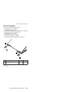
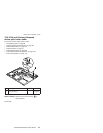
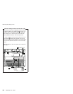
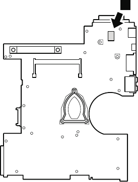
Important notice for handling the system board:
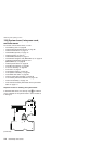
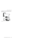
In ThinkPad R50 series, the security chip a is soldered
on the underside of the system board in some models as
in this figure.
a
(continued)
Removing and replacing a FRU
114 R50/R50p, R51 Series


